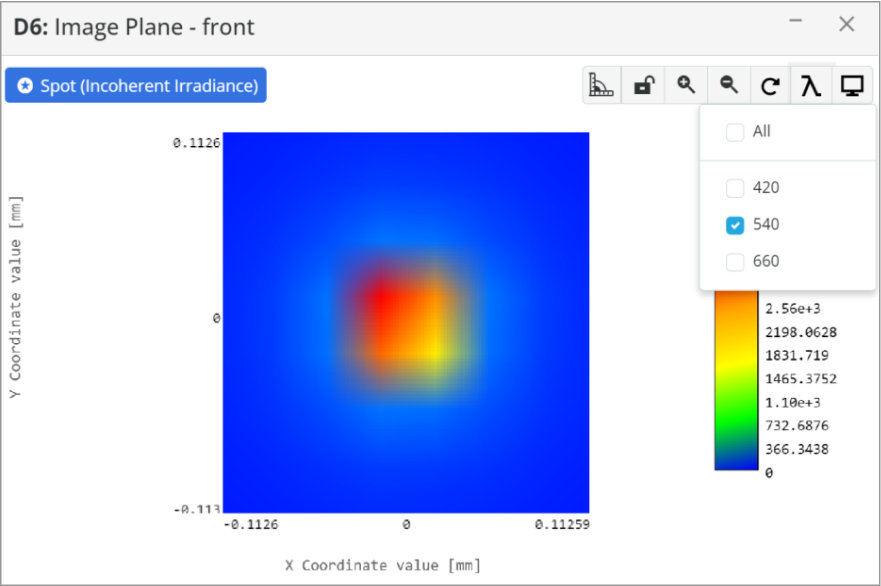
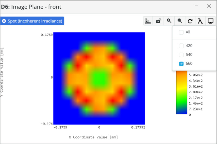
- Light Source
- Plane Wave
- Circular, 5 mm radius
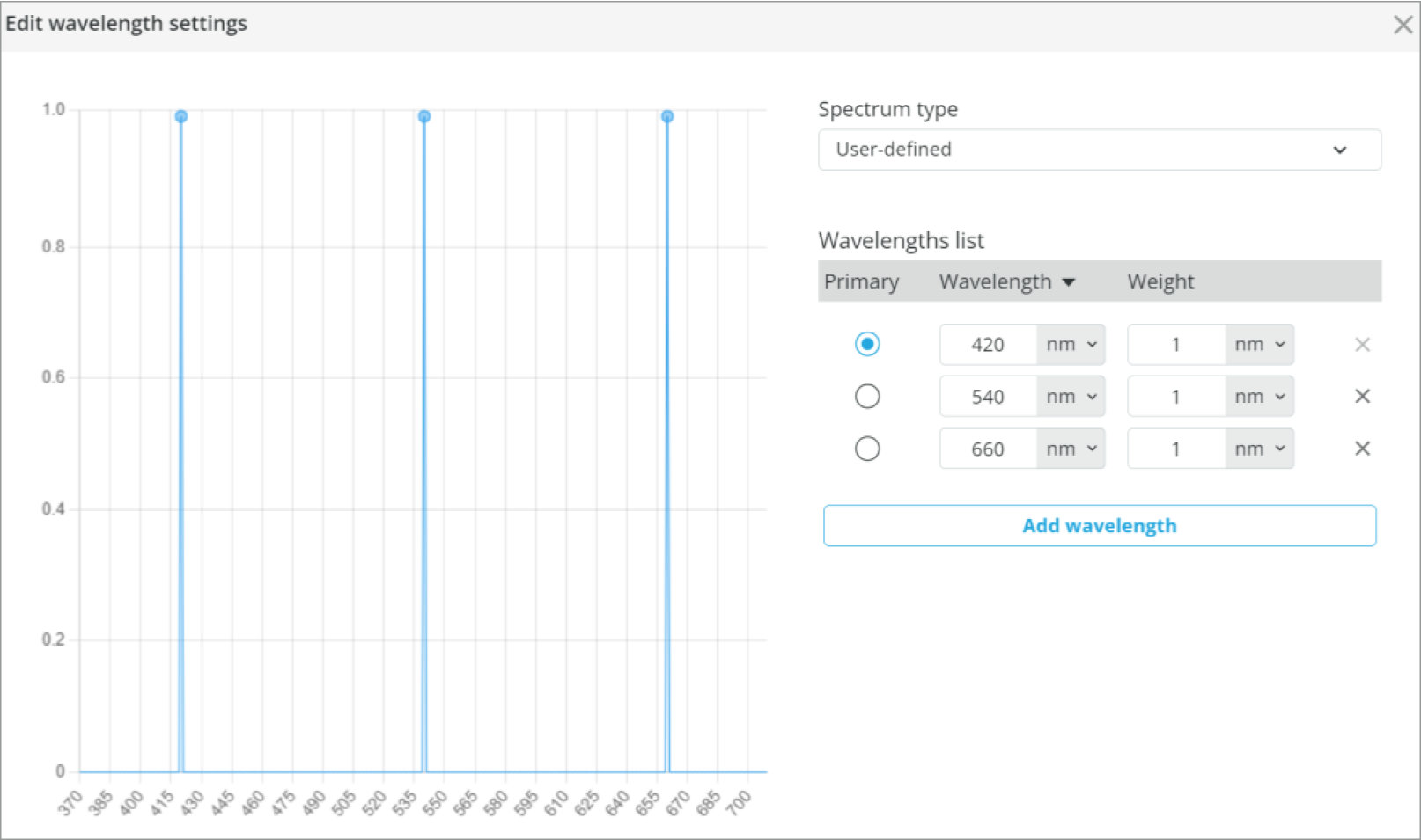
- Wavelength: 633 nm
- Power 1 W
- Unpolarized
- Thorlabs LA1301, 250 mm FL Plano-Convex
- Thorlabs LA1131, 50 mm FL Plano-Convex
- Field Stop, 12.7 mm
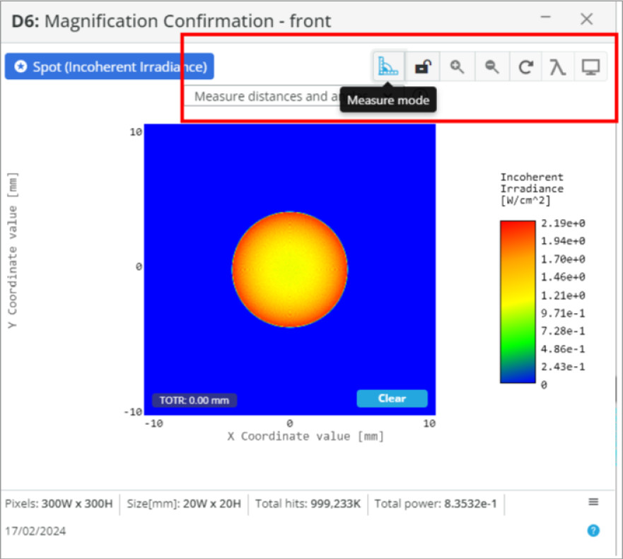
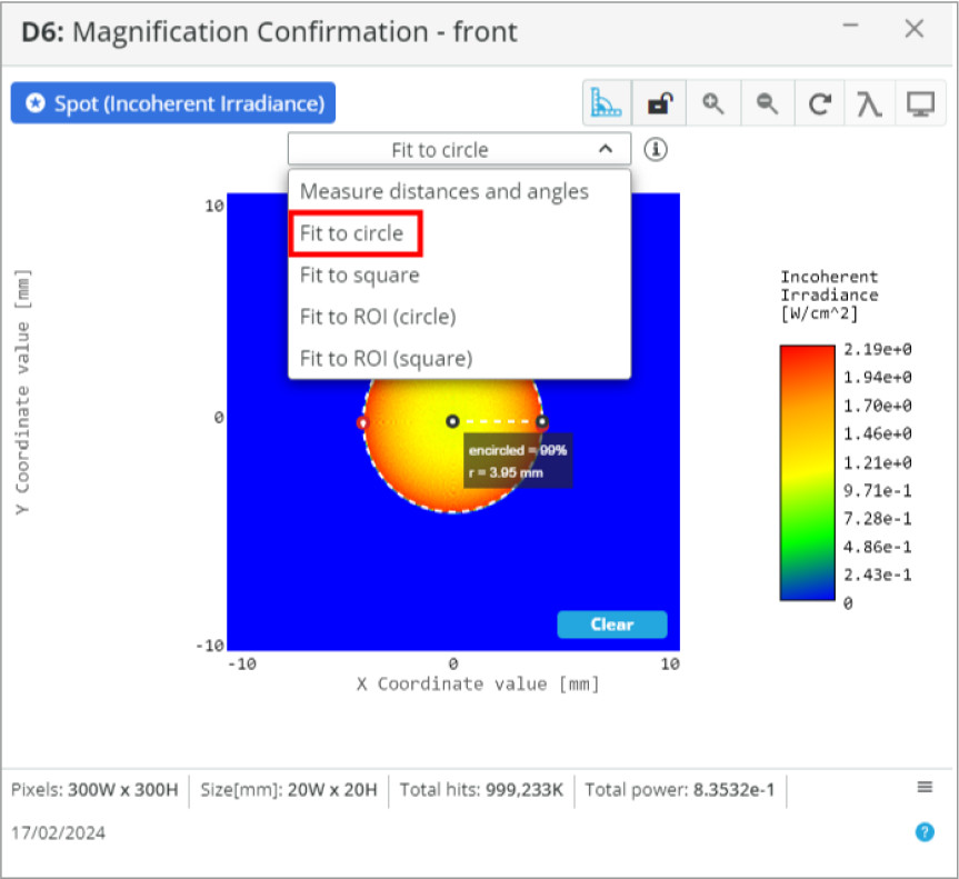
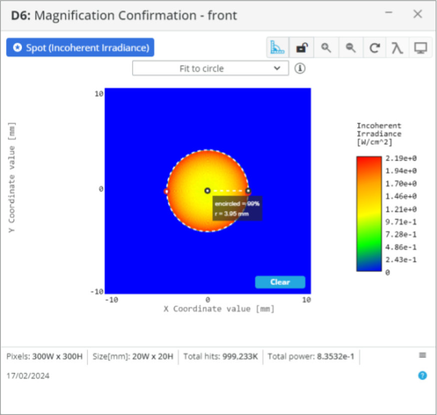
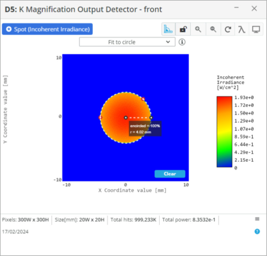
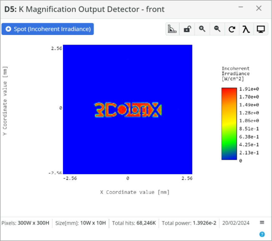
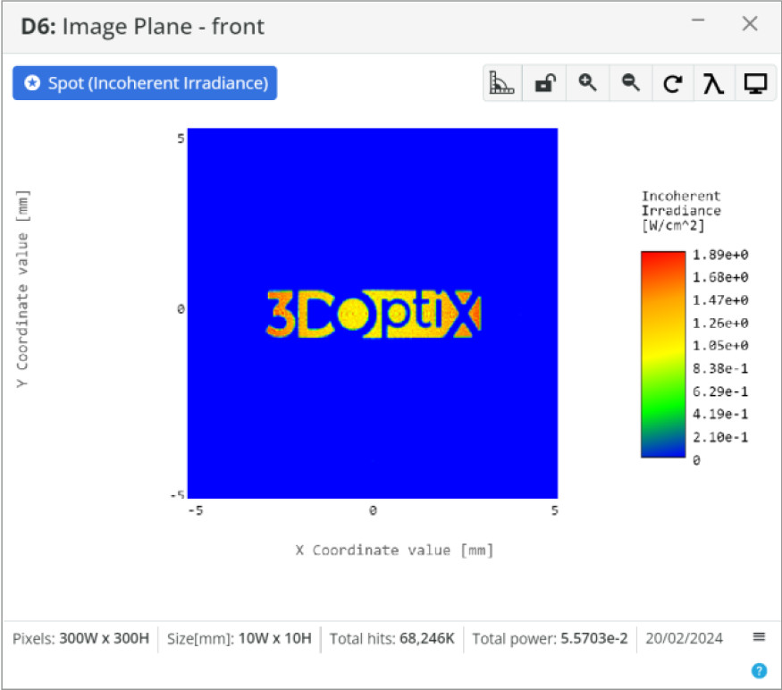
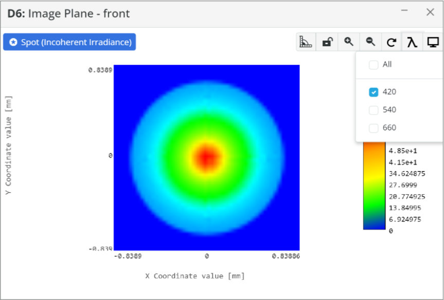
- Detector: Spot Analysis
- Spot: Incoherent Irradiance
- Analysis Rays: 1 million
- 300×300 pixels
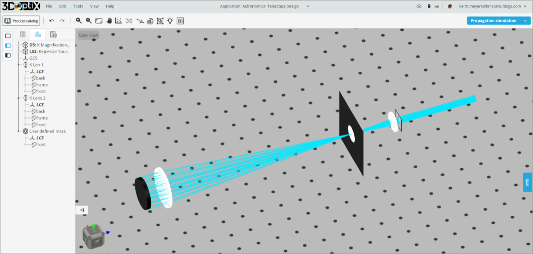
This telescope design can also be used as a beam expander/reducer for laser applications.
Some characteristics of the Kepler telescope:
- Longer system due to the two positive lenses
- Heavier due to the need to flip the image using prisms or mirrors
- Good magnification for astronomical viewing
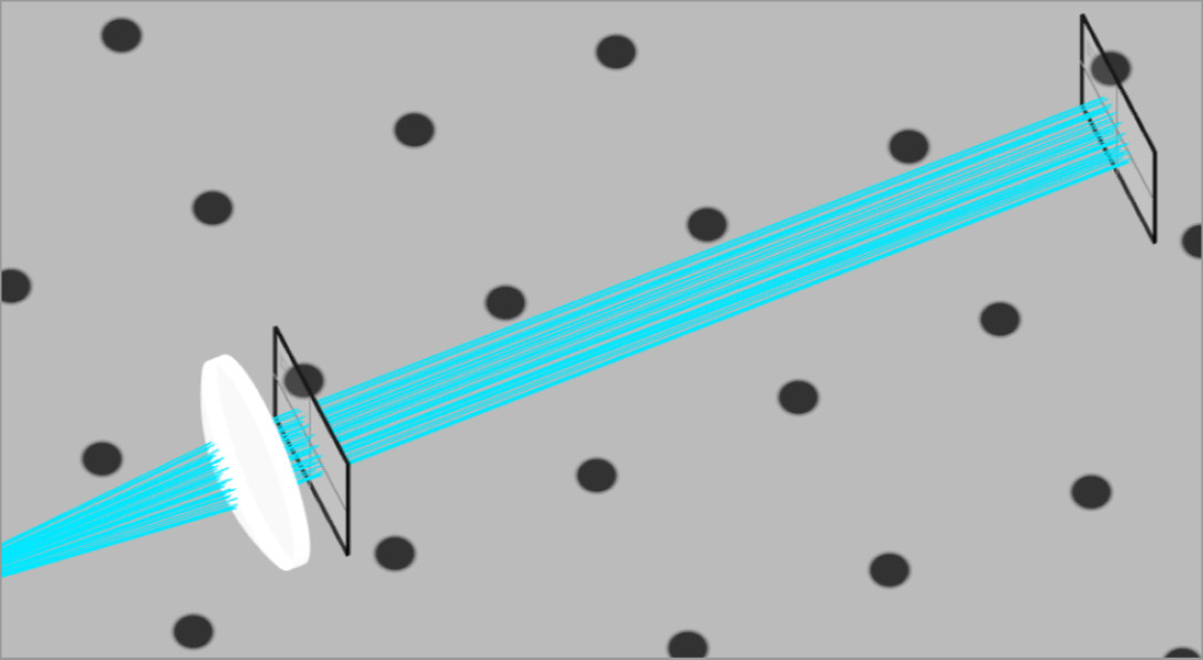
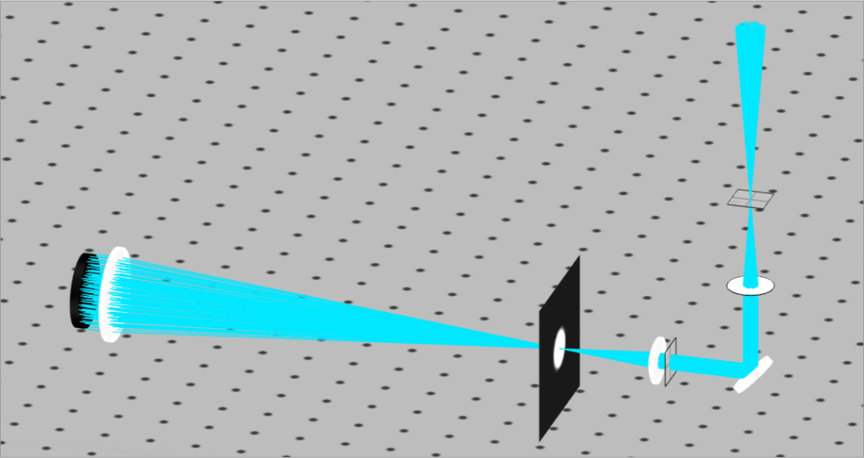
Looking at the image of our optical system, we can see that we have parallel rays entering and exiting the system. Since astronomical viewing occurs over incredible distances, the rays of light at each angle will be collimated. Therefore, we desire a collimated output so that our eye or a camera can image the scene.
For positioning the lenses and determine system performance we can use the simple equations below:
- Lens Separation:D=fObjective+feyepiece
- System Magnification: M=feyepiecefSystem
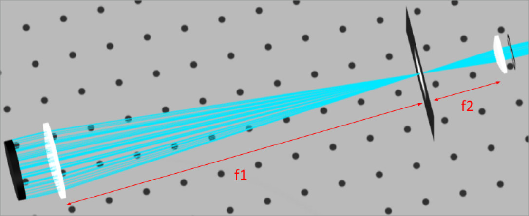
We can see immediately from the image above and the lens separation equation that the positive lenses make the length of the telescope longer than using a negative lens. Negative lenses are used in Galilean telescopes, but they are typically for terrestrial viewing.
Notice that the Kepler telescope is actually benefited from the longer system focal length with increased magnification.
Below are the calculated parameters of the systems. We will later add in more components to complete the design, but for now we will take as fact that the additional components will add 150 mm to the system focal length. The system focal length is the path length from the objective lens to the eye/camera.
This will be shown further down in the analysis.
- Lens Separation:D=250mm+50mm=300mm
- System Magnification: M=50(300mm+150mm)=9.0x
Now that we have our starting parameters calculated we shall analyze the collimation from the on axis collimated light.
We will add an extra detector 100 mm behind the first detector. This will allow us to determine if the lenses are positioned so that collimation is achieved at the output of the eyepiece lens.
