VIRTUAL LAB
Polarization Optics
Approximately 3 hours (self-paced)
- Understand what polarized light is
- Use polarized light correctly in optical simulations
- Utilize polarization effects at optical interfaces
- Incorporate polarization sensitive optics
- Review polarization applications
Polarization States

In reviewing the video, one can see that the electric field vectors can take on infinite phase differences with respect to each other, but only three states can be produced: linear, circular, or elliptical polarization.
Laser sources tend to be linearly polarized due to the gain media used to create the lasing action. LEDs are unpolarized as there is no mechanism to create a preferred polarization state output. Knowing the polarization state of a light source is an important parameter in optical systems. For instance, attenuating light can be achieved using neutral density filters or polarizers. Using a polarizer as an attenuator with an LED would cut out around 50% of the light throughput, whereas a neutral density filter is polarization insensitive. If the system is to produce light for an imaging application, then a polarizer may reduce the output to an undesirable level.
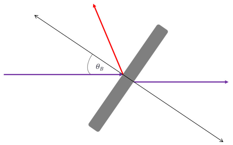
Using optical components, such as windows or beam splitters, at angles other than normal incidence could produce physical effects such as Brewster’s angle. This is the angle at which the reflected light is completely polarized. For laser beam scanning applications this increases the non-uniformity of the laser beam scan area and reduces the peak power under critical requirements.
Polarization States
Polarizers are optics that interact with specific polarization states under rotation and angular offsets. Some polarizers are designed for direct incidence, i.e. for light that is incident normal to the surface, and others for specific incident angles, such as 45 degrees. Polarizers can either absorb or reflect the rejected polarization states.
In a polarizer, the polarization state that is transmitted is based on its polarization axis. Typically, this is indicated by the manufacturer as a line or arrow on the side of the polarizer, but it can easily be experimentally obtained by rotating the polarizer until the maximum amount of light has passed.
The formula to determine how much light has passed when light is incident on a polarizer is given by
1. Itransmitted=I0cos2(θ), this is known as Malus’s Law.
Where theta is the angle between the polarization axis of the polarizer and the polarization direction of the incident light, I0 is the incident light source power, and Itransmitted is the transmitted power.


- Import the file “Polarizer_LS.opt” into the 3DOptix app.
- Click on the analysis portal and select run analysis
- Click on the analysis detector to bring it into its own window
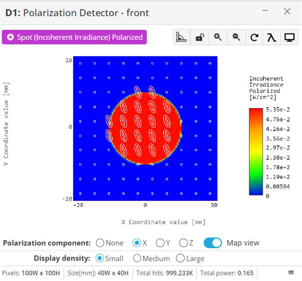
 Notice on the bottom of the window there are four options to view the power for each polarization state; none, x, y, and z
- Select polarization state “None”, x, and y to see how much power is present for each
 We are not interested in the z component as it is not present in these polarization states
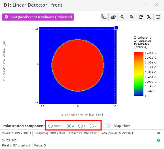
- Record these values in the table below
 The “None” option includes power for all polarization states

The original discovery of polarization of light is attributed to the Dutch scientist Christiaan Huygens in the 17th century. In 1690, Huygens proposed that light consists of waves that propagate through a medium, much like waves in water. He observed that when light passes through certain materials or is reflected at certain angles, its oscillations become aligned in a specific direction.
Huygens’ work laid the foundation for understanding polarization, although the term “polarization” itself was not coined until later. His insights were instrumental in explaining various optical phenomena, including the behavior of light as it interacts with different materials, such as crystals and lenses.
When polarization is referenced to an optical component’s optical axis, the states are referred to as “S” and “P” states. These stand for perpendicular (S) and parallel (P). The “S” stands for “senkrecht” which is German, and translates to “perpendicular” in English.
Otherwise, if polarization is being referenced in a general way we use the terms “horizontal” and “vertical” with some surface (such as a breadboard) being the reference.

- Import the file “Polarizer_Basics.opt” into the 3DOptix app
- Click on the analysis portal and select run analysis
 There is a polarizer inserted into the optical path to change the amount of light that makes it to the detector. The extinction ratio is 60 dB, so very little light from the opposite polarization will make it through to the detector when aligned with the polarization axis of the light source.
- Change the “Z” angular component of the polarizer in the simulation file to the positions specified in the table below. This simply rotates the polarizer
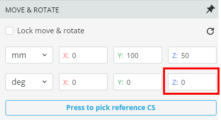
- Record the resulting power for each polarization state by changing the angle and running the analysis
- Keep the file open for the next exercise
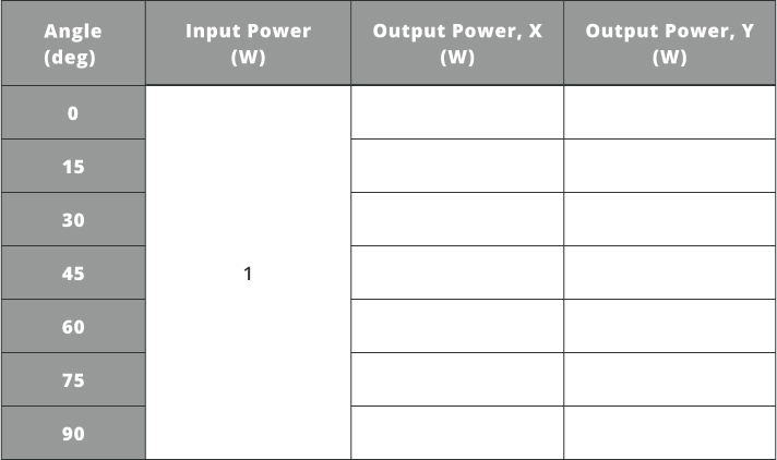
Note that the power on the detector will always be less than the total input power because of the extinction ratio of the polarizer and Fresnel reflections. Finally, if the polarizer is rotated to the minimum transmission angle for linearly polarized light, all light will be blocked except for the amount passed, which is dictated by the extinction ratio.
Edwin H. Land’s invention of Polaroid material in the 20th century marked a significant milestone, providing a practical means to manipulate polarized light. By selectively absorbing light waves oscillating in one direction while allowing others to pass through, Polaroid material became the foundation for modern polarizers.
Today, polarizers play indispensable roles in various fields, from photography and display technologies to scientific research, offering precise control over the polarization of light and enabling countless technological advancements.

- With the previous simulation file still open, click on the polarizer in the 3D layout and duplicate it
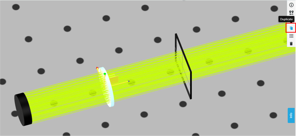
- Rename the new one “Polarizer 2”
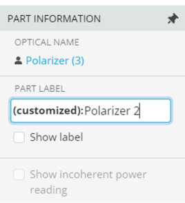
- Position it at [0,100,75]

- Change the rotation angle to the values in the table below, run analysis, and record the power
 Notice that there are locations of minimum and maximum transmission for both a single polarizer and dual polarizers
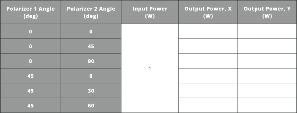
- After the table is filled out, add a third polarizer in the same manner as the second from the above step
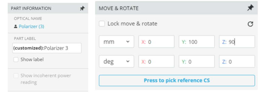
- Change polarizer 2 and 3 angle to z = 90
 Polarizer 1 should be z = 0 degrees

- Run analysis and observe the power on the detector for both “x” and “y” polarization states
 We now have “crossed” polarizers, between polarizer 1 and 2/3, and should not see any transmission to the detector
- Now change polarizer 3 angle to z = 0
- Run analysis and observe the power on the detector for both “x” and “y” polarization states
 We still have crossed polarizers, between polarizer 1 and 2, and should not observe any power still on the detector
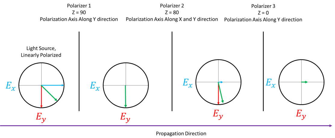
- Now change polarizer 2 angle to z = 80 and polarizer 3 to z = 90
- Run analysis and observe the power on the detector for both “x” and “y” polarization states
 We now have light on the detector even though polarizers 1 and 3 are crossed. This is contradictory.
The effect we are seeing is that the polarization state is no longer referenced to the original light source’s polarization axis, but to the previous polarizer’s polarization axis.
When the second polarizer was rotated to 80 degrees, we then generated not a 90-degree angular difference between the incident light and the polarization axis, but a 10-degree angular difference. Therefore, some light will pass through the second and third polarizers as the light polarization and the third polarizer polarization axis are no longer 90-degrees in angular difference.
In reality, there are always two orthogonal electric field vectors that create the total polarization even after transmission through a polarizer. See the video in the beginning of this virtual lab for a refresher on this.
Note that the electric field vectors don’t convey the ratio of energy in each state, only the sum polarization. The magnitude shown in the final step (after polarizer 3) in Figure 3 below is only for illustrative purposes of the power that transmits through the third polarizer.
Polarization Sensitive Surfaces and Phenomena
In addition to substrate and coating specific effects, there are physical phenomena that can be utilized to exploit light polarization. Brewster’s angle is a physical phenomenon where, at a certain angle, the reflected light is completely polarized.
Where nx is the index of refraction for medium x.

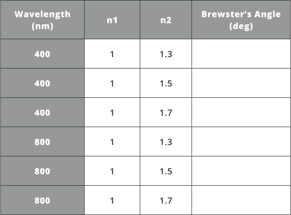
- Calculate Brewster’s angle for the various wavelengths and indices of refraction in the table below using equation 2
- Import the file “Brewster.opt” into the 3DOptix app
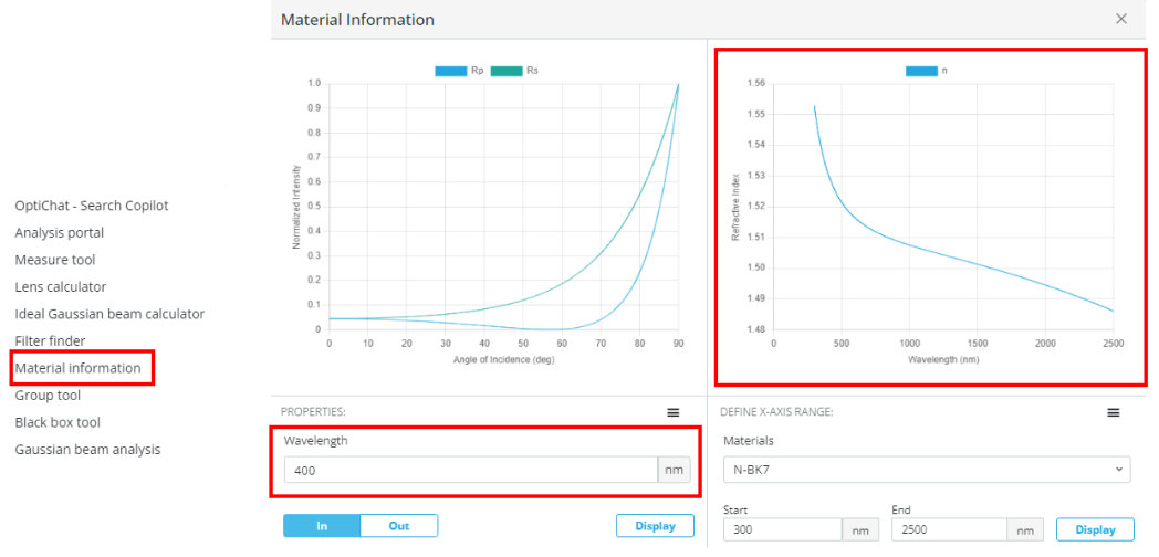
- Using the material tool, find substrates that are close to the index of refraction from the table above.
- Fill in the table below for the substrate used, index of refraction of the medium, and reflected and transmitted power at the specified angles
 The offset angles are displaced from Brewster’s angle, e.g. if Brewster’s angle is 56 degrees and the angle is +1, then the angle of the Brewster’s window would be 57 degrees
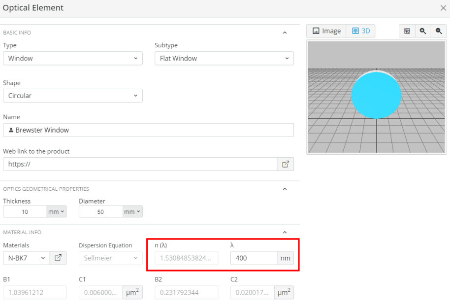
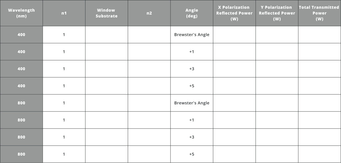
- Now change the light source polarization to 90 degrees corresponding to a vertically polarized linear state and fill out the same table with the new polarization state
 Notice that this polarization state does not exhibit the same behavior as the other state
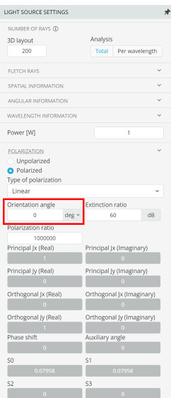
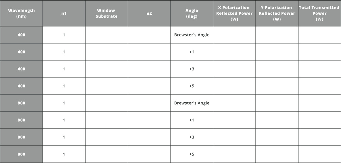

- Import the file “Beam_Sampler.opt” into the 3DOptix app
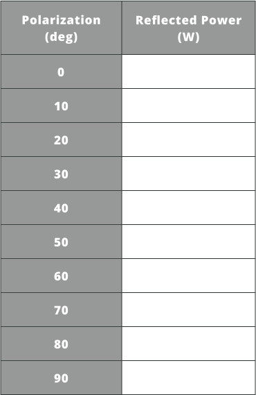
- As the incident polarization angle changes, the reflected power will change. Change the polarization angle of the light source using the light source settings
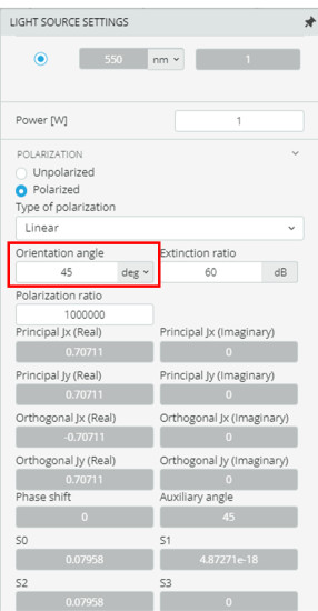
- Click on the analysis portal and select run analysis
- Fill in the table below
Polarization Applications
The phase shift from a bi-refringent substrate can be calculated using equation 3 below.
Where d is the thickness of the substrate, nx is the index of refraction along the slow and fast axis, and λ is the design wavelength.

- Import the file “WP_Circular.opt” into the 3DOptix app
- Using equation 3, calculate the parameters needed to create a quarter waveplate to circularly polarize a linear light source at 660 nm
 Use the user defined object that is in the 3D layout
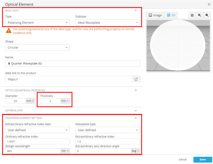
- Once the quarter waveplate is designed and implemented, click on the analysis portal and run the analysis
- Click on the detector window and select the map view
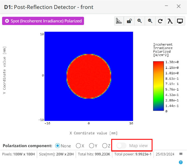
- If the quarter waveplate was implemented correctly, the map view will show circular polarization over the spatial intensity field
 The polarization state will not be perfect, but should look somewhat elliptical and close to circular
 Try 1.301365 and 1.31 for the two indices and 12.7 mm for the thickness if other values are not working
