Telescopes

VIRTUAL LAB

Telescopes

Course Overview
This pre-lab assignment aims to introduce students to telescopes, their fundamental principles of operation, and the optical aberrations that can affect the quality of astronomical observations. Students will gain a deep understanding of the various types of telescopes, their components, and how they are used to observe celestial objects. The course will cover both refractive and reflective telescopes, and specific analysis of each.
Course Duration

Approximately 3 hours (self-paced)

Learning Objectives
By the end of this pre-lab assignment, students should be able to:
  • Understand the Basic Principles of Telescopes
  • Explore Different Types of Telescopes
  • Investigate Optical Aberrations
  • Conduct Practical Experiments
  • Learn how to mitigate different types of aberrations
Course Outline - Introduction to Telescopes
Telescopes are instruments used to observe and study objects such as stars, planets, galaxies, and nebulae. The word telescope comes from the Greek words tele, meaning “far off,” and skopein, meaning “to look at.” The basic principle of operation for all telescopes is to gather and focus light from a distant object. The two main types of telescopes are refracting telescopes and reflecting telescopes.
Telescopes can be used for both terrestrial and astronomical viewing. The difference mainly being their ability to magnify objects that are far away. Terrestrial telescopes, such as the Galilean telescope, can be used for observing objects on Earth and in our solar system but are not suited for viewing galaxies. Astronomical telescopes, on the other hand, are able to generate large angular magnifications that allow viewing of the most distant astronomical objects.

Basic Principles of Telescopes

Telescopes, whether refracting or reflecting, operate on fundamental principles involving an objective lens or mirror to gather and focus light and an eyepiece lens that re-collimates the output. The focal lengths of the objective and eyepiece lens influence magnification, and different eyepieces can be used for varying magnification levels. The entrance aperture, diameter of the limiting element such as the objective, impacts the amount of light collected, affecting brightness and detail in images. The exit aperture, where the eye is placed, is located after the eyepiece, where the fields of view meet in a Keplerian telescope. In a Galilean telescope, this is inside the telescope due to the diverging light the negative lens produces. The position of the eye after the eyepiece lens is known as the eye relief.

Fig. 1. Example of a Keplerian telescope. A refractive astronomical telescope design.
The optical elements in a telescope, either lenses or mirrors, must be placed so that incident collimated light at the objective is collimated coming out of the eyepiece well. To do this we simply add the focal lengths of the optics together to generate the distance between them.
1. D=f_{objective}+f_{eyepiece}
At this separation, the system will re-collimate the light and the telescope will operate properly.
The angular magnification is a function of the lenses used and is due to the change in angle of the input light from the source and the output light that enters the eye or camera. The negative sign is convention for determining if the image is inverted or not.
2. MP=-{\frac{\theta_{input}}{\theta_{output}}}
This can be more difficult to determine, so we can make a paraxial approximation and simply equate the magnification to the focal lengths of the optical components.
3. MP=-{\frac{f_{objective}}{f_{eyepiece}}}
Experiment 1

Telescope Parameters

Building simple telescopes is a straightforward process using equations 1 and 3 from above.  With this, we can calculate some of the important parameters that will drive the performance of our telescope.  By changing the focal length of the objective and eyepiece lenses, we can generate different telescope lengths and magnification levels.  The next step will be to use optical design software to analyze a Keplerian and Galilean telescope.
Exercise 1
  • Using equations 1 and 3 from the previous section, fill out the table
  • Depending on what the purpose of the telescope is these parameters can be varied to conform to the needed performance. However, there are no independent variables, so changing one parameter, such as the focal length of the eyepiece, necessarily changes the others.
Extra information
Early telescope designs primarily include refracting telescopes, which use lenses to gather and focus light. The development of the telescope is credited to several individuals, most notably Hans Lippershey, Zacharias Janssen, and Jacob Metius, who were spectacle-makers in the Netherlands. However, the Italian astronomer Galileo Galilei is often credited with the earliest recorded use of a telescope for astronomical purposes.
Exercise 2
  • Click on the Keplerian objective lens and determine the BFL at the wavelength used in the Kepler LS1
  • Repeat this for the Keplerian eyepiece lens, but for the FFL (ignore the negative sign)
  • Record the total distance, D, that needs to separate the objective and eyepiece lens
  • Calculate the magnification, M, using equation 3
  • Repeat the above steps for the other design, the Galilean telescope
  • Next find the exit pupil location. This is where the three Keplerian LSs after the eyepiece lens cross and the spatial size is minimized. Do this by moving the detector and measuring the spatial size of the light field using the measure mode tool.
  • Record this value in the table
  • Finally, the angular resolution will be determined.  Add a paraxial lens 25 mm in diameter with a focal length of 25 mm where the Keplerian and Galilean detectors are positioned
  • Reference and position the detectors 25 mm from their respective paraxial lenses
  • Reduce the detector size to 2×2 mm
  • Using LS2 for both telescopes reduces the Y-angle until the two spots are overlapping.  Click between the spots in the analysis window to bring up the cross section and confirm that the spots overlap
  • Record this angle
  • We now have the important parameters for both the Galilean and Keplerian telescopes
  • Keep the simulation file open for the next exercise
  • The exit pupil is also the eye relief of the system. A longer eye relief can be better as small movements of the eye when viewing do not move it appreciably out of the ideal viewing location. The angular resolution will be our limiting factor for observing very close objects such as binary star systems, and smaller is always better.
Extra information
Galileo’s telescope, which he constructed in 1609, featured a convex objective lens and a concave eyepiece lens. This simple design allowed him to achieve low magnification but significantly enhanced his ability to observe celestial objects. With his telescope, Galileo made groundbreaking astronomical discoveries, including the moons of Jupiter, the phases of Venus, sunspots, and the mountains and craters on the moon.
Early telescopes were characterized by their relatively small apertures and low magnification capabilities compared to modern telescopes. These early instruments were often constructed with simple wooden or metal tubes and lacked the sophisticated optical coatings and precision machining techniques used in contemporary telescope manufacturing.
Despite their limitations, early telescopes revolutionized our understanding of the universe and paved the way for advancements in astronomy and scientific inquiry. They played a crucial role in disproving the geocentric model of the universe and supporting the heliocentric model proposed by Nicolaus Copernicus. Over time, telescope designs evolved, leading to the development of more sophisticated optical configurations, including reflecting telescopes and compound telescopes, which combine lenses and mirrors.
Exercise 3
  • Go to the analysis portal and run analysis
  • Click on the analysis window
  • In the analysis window, select each wavelength individually and measure the spot size for all the wavelengths using the measure mode tool
  • The difference in spot sizes at the focal plane will appear as a halo of colors corresponding to the mismatching of the indexes of refraction.
  • By using different lens focal lengths and optical substrates we can reduce the spot size variation at the image plane.  This will help keep this aberration type small.
Extra information
Chromatic aberration is an optical phenomenon wherein different wavelengths of light are refracted differently by a lens, causing them to focus at slightly different points. This results in colored fringes or halos around objects, particularly noticeable in high-contrast scenes.
There are two main types: longitudinal, which affects the convergence of different colors at the focal plane, and lateral, which causes color fringes around object edges. This aberration can degrade image quality, reducing sharpness, contrast, and color accuracy.
To mitigate chromatic aberration, optical designers use techniques such as apochromatic lens designs, employing extra-low dispersion glass. While chromatic aberration is a common challenge in optical systems, advancements in lens design and technology have enabled effective mitigation strategies in modern optical instruments.
Experiment 2

Reflecting Telescopes

Reflecting telescopes have all the basic performance parameters of refractive telescopes.  However, there are unique benefits and challenges that are inherent in their design.  The primary mirror can be made larger than a traditional lens, but the secondary mirror blocks some of the light incident into the telescope.  Newtonian telescopes have a large primary mirror and a smaller secondary mirror that redirects the light out of the optical system.
Fig. 2. Example of a Newtonian telescope. A reflective astronomical telescope design.
Exercise 4
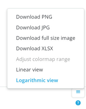
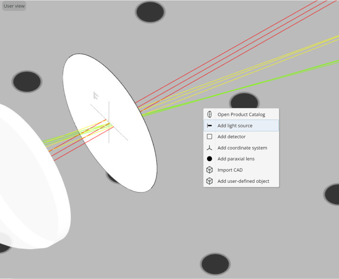
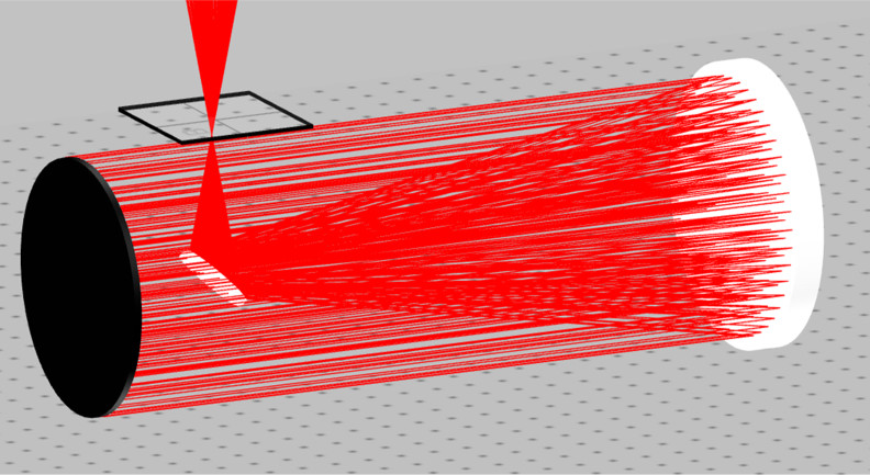
  • The first task is to determine the light throughput for different sizes and positions of the secondary mirror. Go to the analysis portal and run analysis.
    Ensure you select None for the polarization component to record the total power on the detector
  • Record the power in the table for configuration 1
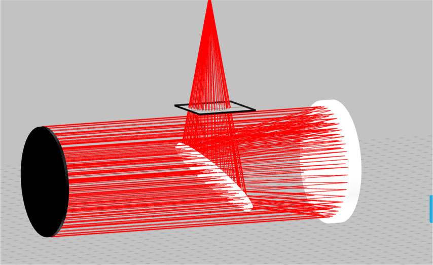
  • Next, change the size of the elements to increase the light throughput Secondary Mirror Diameter = 120 mmSecondary Mirror Position, Y = 95, Z = 200
  • Record the new power in the table for configuration 2
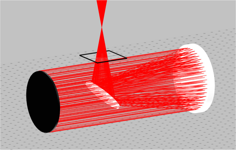
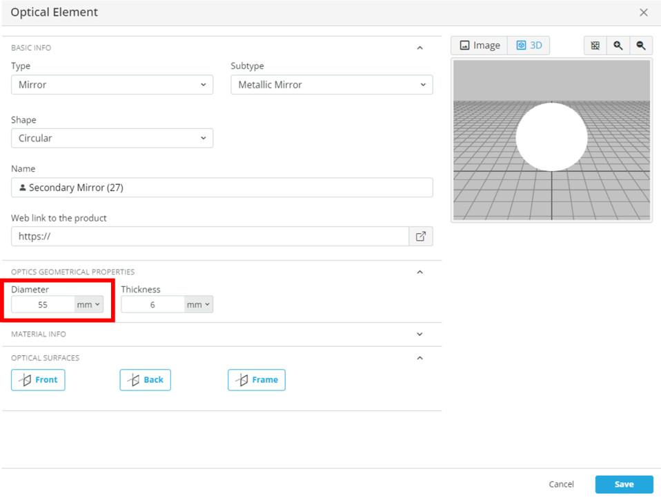
  • Change the secondary mirror for the final configuration Secondary Mirror Diameter = 55 mm Secondary Mirror Position, Y = 97, Z = 100
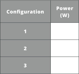
  • Record the new power in the table for configuration 3.
    Notice in the third configuration that the focus is just outside the optical system
  • Keep the simulation file open for the next exercise
We want to maximize light through the system to get the best brightness and resolution possible.  Too little light will create a dim image and make it harder to see fine details.
Exercise 5
  • With the Newtonian reflector in a nominal setup the secondary mirror can be further optimized to define the FOV.  Add three light sources and place them collocated with Newtonian LS1.
  • Name the light sources “Newtonian LS2”, “Newtonian LS3”, and “Newtonian LS4”.
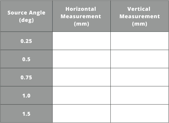
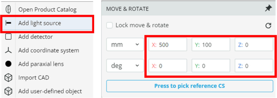
  • Change the light source angle to the following.  We will define a 1.5 degree FOV. LS2: X Angle = 1.5 degrees LS3: X Angle = -1.5 degrees LS4: Y Angle = 1.5 degrees
  • Select the secondary mirror and make the front surface a detecting surface by clicking on it.
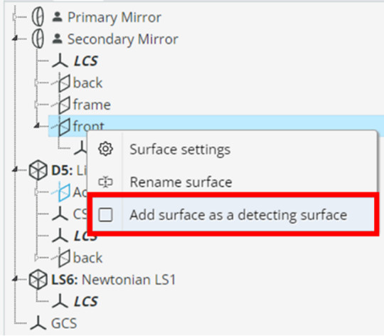
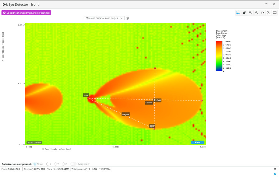
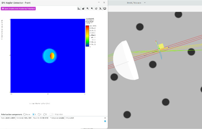
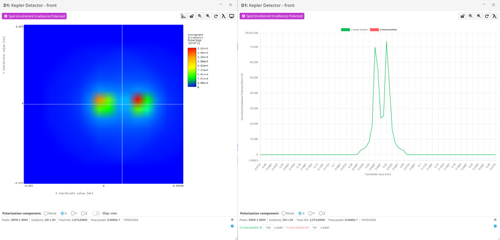
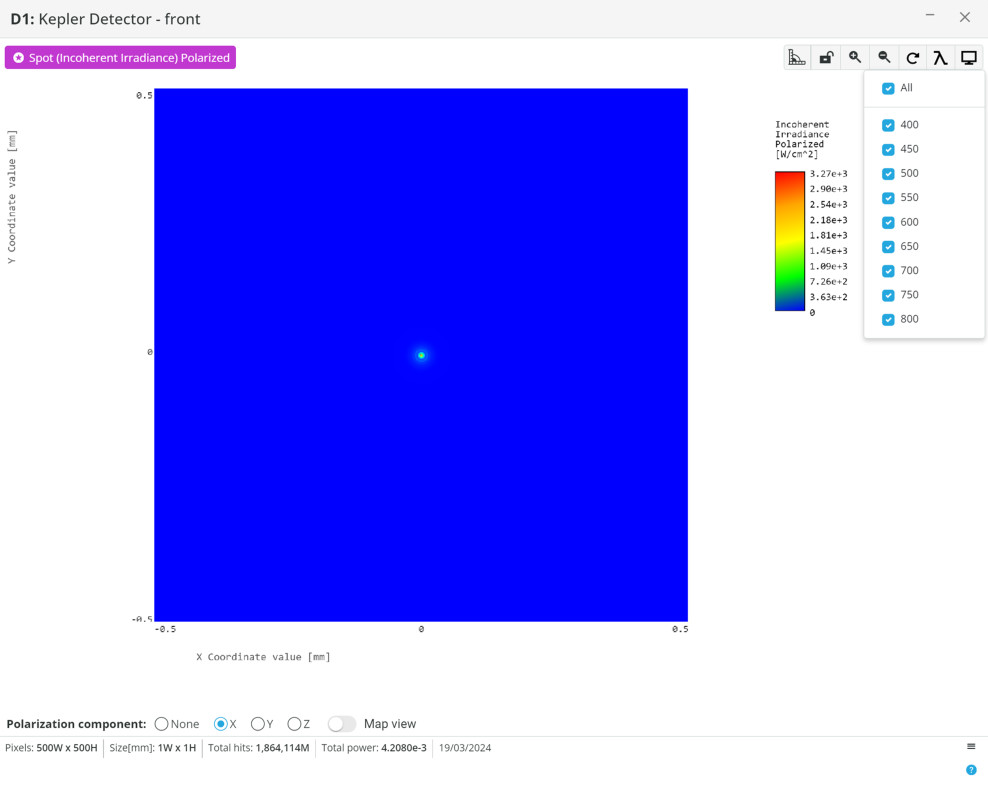
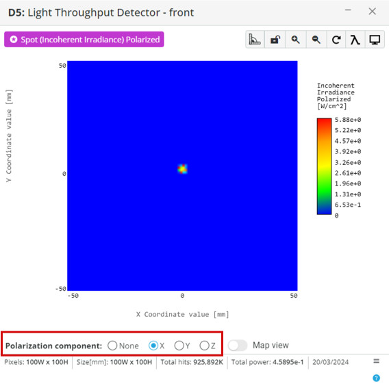
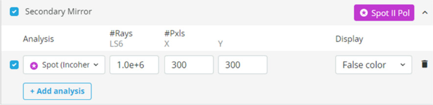
  • Go to the analysis window and change the secondary mirror detector. Spot (Incoherent Irradiance) Polarized 1e6 light source rays 300×300 pixels
  • Run analysis and click on the analysis window to bring it to its own window.
  • Notice the secondary mirror is now too small to capture the light from all source angles fully.
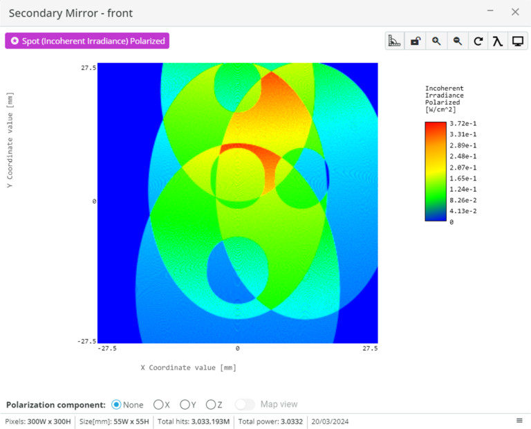
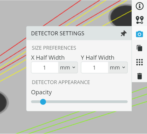
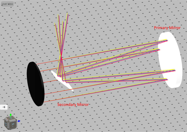
  • Click on the secondary mirror, select settings, and change the diameter. Repeat this while re-running the analysis until the light from all light sources is incident on the mirror. Note that you may need to change the Y position of the mirror to both minimize the secondary mirror size and capture all the light
  • Compare the light throughput of the final configuration to configuration 3 in the table from exercise 4.
  • Keep the simulation file open for the next exercise.
Extra information
The secondary mirror in a Newtonian telescope serves many purposes and must be optimized. It serves the critical role of redirecting light gathered by the primary mirror toward the telescope’s eyepiece or imaging device. Typically, a fraction of the size of the primary mirror, the secondary mirror reflects the light at a 90-degree angle away from the optical system, allowing for observation. The size of the secondary mirror is carefully determined to optimize the telescope’s performance, balancing factors such as light transmission, image brightness, and resolution.
Exercise 6
  • The final piece of the Newtonian reflector is to insert an eyepiece and determine the magnification. Equations 1 and 3 determine the separation between the primary mirror and eyepiece, and the magnification is the same as for the refracting telescopes.
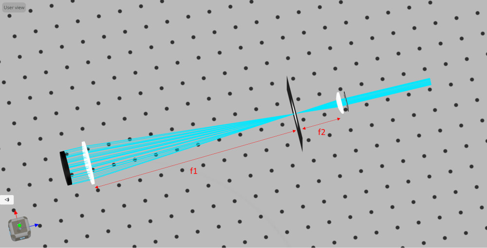
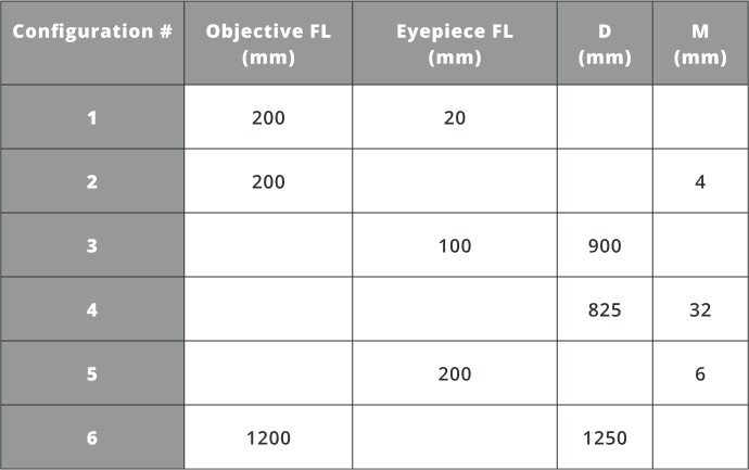
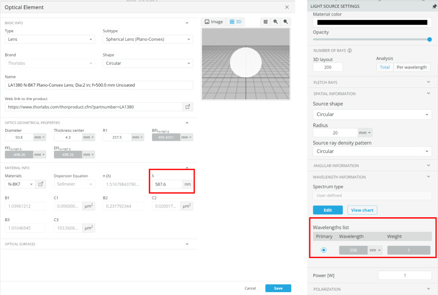
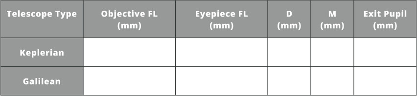
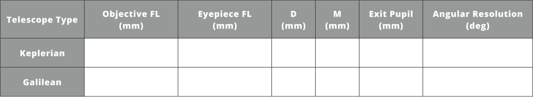
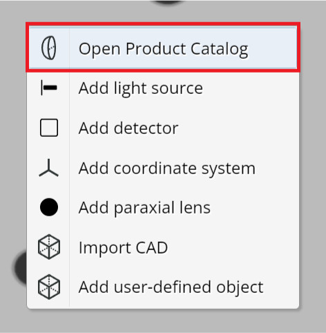
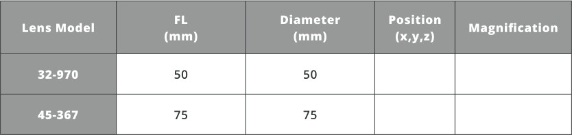
  • Insert the eyepiece lenses from the optical catalog from the table below and fill in the missing information. Note that the equation 1 distance is the folded path from the primary mirror to the secondary mirror and from the secondary mirror to the focus
  • Greater magnification also reduces the FOV which is a tradeoff for this system parameter.  If viewing a planet in detail is desirable we would want a larger magnification, but if we want to see multiple galaxies we would need a larger FOV and therefore a smaller magnification.
Exercise 7
  • Go to the analysis portal and run analysis
  • Click on the analysis window to bring it into its own window
  • In the analysis window select each source angle individually and observe the shape of the spot
  • Change to logarithmic view to more easily see the coma present in the output
  • Determine if the comatic aberration linearly increases with the source angle by measuring the horizontal and vertical dimensions by filling out the table.
  • The numbers measured for the table above simply show that the coma is greater at larger incident angles as they hit the parabolic mirror. Aberrations are more easily analyzed when compared to multiple optical systems to compare relative performance, or when using a camera with a specific pixel pitch. If the aberration, or sum of aberrations, creates a spot larger than the pixel pitch of the camera, then you can expect performance degradation.
Extra information
Coma aberration is an optical distortion commonly observed in reflective telescopes, particularly those with fast focal ratios. It occurs when off-axis light rays focus at different points, resembling the shape of a comet’s tail, hence the term “coma”. This aberration leads to distorted star images near the edges of the field of view, with stars appearing elongated or comet-like instead of sharply focused points. Coma can significantly degrade image quality, particularly in wide-field observations where objects are located away from the telescope’s optical axis. To minimize coma, optical designers utilize corrective elements such as parabolic mirrors or specialized coma correctors, which help ensure that off-axis light rays converge to a single point, producing more uniform and sharp star images across the entire field of view. While coma remains a challenge in reflective telescopes, especially those with large apertures and fast focal ratios, careful design and corrective measures can effectively mitigate its impact, enabling astronomers to obtain clearer and more accurate observations of celestial objects.
Analysis and Conclusion
Throughout this virtual lab on telescopes, students have gained valuable insights into the principles of different types of telescopes. The experiments conducted using a virtual optical simulator have allowed students to explore the underlying principles of telescopes, their properties, and their advantages.
References:

Below are some references for telescope types and some additional educational information

Orion Telescopes

High Point Scientific

Building a Simple Telescope

Telescope Aberrations

Assessment
NA
Resources
The student requires an account in the 3DOptix system.
Synopsys
This telescope lab course provided valuable insights into the design, performance, and challenges associated with telescopes. It demonstrated how optical aberrations can affect observations and emphasized the importance of innovative solutions in the field of astronomy. These skills and knowledge are crucial for anyone interested in pursuing a career in astronomy, optical engineering, or related fields.
mascot-1-1

3DOptix works
only on desktop!

Please go to 3doptix.com on a
desktop device, using the
Chrome or Edge browser

Available on January 30th, 2023