Snell’s Law

VIRTUAL LAB

Snell’s Law

Course Overview
This laboratory course focuses on the fundamental principles of light reflection and refraction. It provides hands-on experience for students to understand how light behaves when interacting with various optical surfaces and media. The course explores Snell’s law, the index of refraction and total internal reflection through a series of engaging experiments.
Course Duration
Approximately 3 hours (self-paced)
Learning Objectives
By the end of this pre-lab assignment, students should be able to:
  • Understand the law of refraction using Snell’s law.
  • Calculate angle of refraction and beam displacement.
  • Determine the index of refraction for different materials.
  • Investigate total internal reflection and its applications in light pipe and optical fibers.
Course Outline - Introduction to reflection and refraction:
When light travels through transparent materials, it interacts with the atoms and molecules. The light is an electromagnetic wave, so it excites oscillations in the charges in the materials. Since the wavelength of the light is much larger than the size of the charges, the light senses the averaged effect over many charges. This interaction slows down the light, so the speed of light in a material depends on the material properties. This value, known as the “index of refraction”, has a slightly different value for each color and allows to faithfully describe the interaction between light and the material. The index of refraction of the vacuum is 1 for all wavelengths. All other conventional materials have a higher index of refraction, which indicates that the light travels at a slower light speed than the speed of light in vacuum. For example, the index of refraction of water is about 1.3 and most types of glass have an index of refraction of around 1.5.

Basic Principles of Zoom Systems

When light travels from one medium to another, it changes its direction. The change in the direction of the light beam is related to the index of refraction according to:
\dfrac{sin(\theta_1)}{sin(\theta_2)} = \dfrac{n_2}{n_1}
Where, n_1 and n_2 are the indices of refraction of the first and second materials, respectively. This law is illustrated in Fig. 1, where we can see the input beam traveling in air, entering glass and changing the direction of propagation according to Snell’s law. In short, when light enters from a less dense material to a denser material it will bend towards the normal.
Fig. 1. Ray tracing of light traveling from air into glass shows a change in the direction of propagation following Snell’s law.
When light interacts with a square piece of material, the light will exit at the same angle as it enters but will be shifted in space. The beam of light preserves its direction as long as the input and the output surfaces are parallel to each other. The light trajectory is displaced from its original trajectory and this displacement is a function of the index of refraction of the material. This is illustrated in Fig. 2.
Fig. 2. Displacement of a light beam from its original trajectory due to a transparent material.
Experiment 1

Snell’s Law and Measuring Beam Displacement

In this experiment, we will demonstrate the Snell’s law using a simple slab, which is made up of a specific material and has a certain thickness. Afterward, we will tilt the slab to determine the beam displacement as it exits the slab. The system used to determine the displacement and demonstrate the Snell’s law consists of a monochromatic light source, a thick plate and a detector. Such a system can also be used to determine the index of refraction.
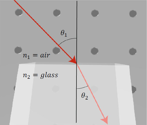
Exercise 1: Setting up a light source, a slab, a detector and verifying Snell’s law
  • Import the file “Ex_1_Snell_Law_Start.opt” into the 3DOptix app. At this stage, only a light source is present. 
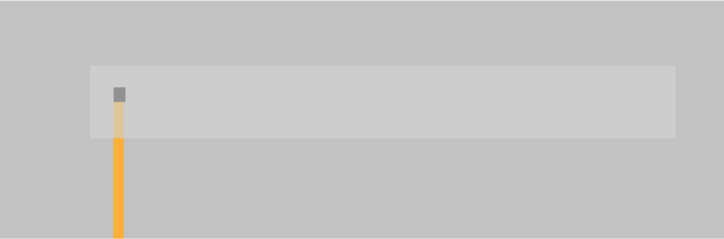
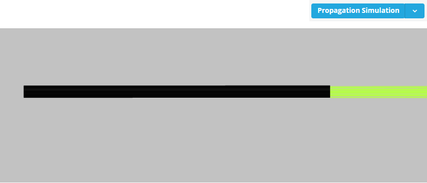
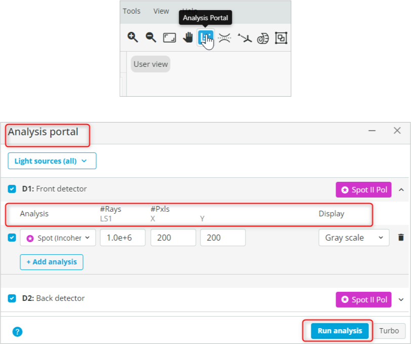
If you don’t see the light rays, then you should click on the Propagation Simulation button, which is available in the top right corner.
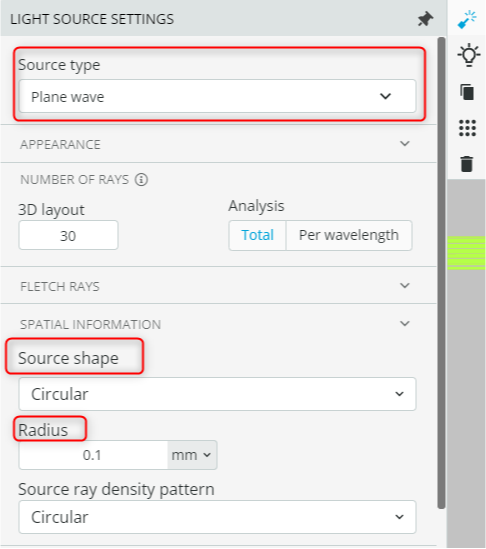
  • Open the light source settings and under “Source type”, check the definition of the source. The source is a circular plane wave with a diameter of 0.2mm. The source settings can be accessed by clicking on the source object. Then click the “Light source settings” option that appears on the ribbon available on the right-hand side of the source.
  • We keep the source monochromatic by defining only a single wavelength at 550nm. This setting is also accessible under Light source settings.
  • Right-click on the viewport background and select User-defined object. This will open an Optical Element window. Add a flat window by performing the following tasks:
    • Under “BASIC INFO”, change the type to a “Window” and Subtype to “Flat Window”.
    • Change the name of the object to “Optical Window”.
  • Change the thickness of the window to 10mm under Optics geometrical properties.
  • Change the material of the window under “Material info” to N-BK7 (SCHOTT).
    • This is done by clicking the material and searching for the desired material.
  • Finally, click save to add the object as shown below.
  • Put the optical window 10mm away from the light source. This is achieved by first clicking the optical window and then accessing the ribbon on the right-hand side and clicking the Move/Rotate option. The coordinates are shown below:
  • Add a front detector by right-clicking on the viewport background and selecting Add detector. The size of the detector can be changed by accessing the detector settings option available on the ribbon. The access to the  detector and detector settings are shown below along with the detector coordinates.
  • Select the front detector and duplicate it. This is accomplished by right-clicking and then selecting “Duplicate”. Change the coordinates of the new detector to the ones shown below. We name this detector “Back Detector”.
  • Rotate the light source to -10 degrees. This is done by changing the X rotation/tilt as shown below.
  • Click Propagation Simulation. The system should look similar to the one shown below.
  1. Calculate theoretically the angle of refraction for various angles of incidence using Snell’s law as mentioned above
  • Open the Analysis Portal and Run analysis. Detector settings are shown below.
  • Click on the front detector window to enlarge it. Now position the cursor around the center of the beam and record the y coordinate as shown below. Similarly, do it for the Back detector.
  1. Use the following equation to calculate approximately the angle of refraction and then the refractive index of the material and fill the table below:
Angle\space of\space Refraction = \tan(\dfrac{Back\space Detector(Y_{cord})-Front\space Detector(Y_{cord})}{Thickness\space of\space the\space window})
Extra information
Snell’s law or the law of refraction, describes the relation between the angle of incident of light to the angle of refraction. The first formulation for the relation between angles of refraction was formulated by Ptolemy, an ancient mathematician in Alexandria, Egypt. The relation was discovered and rediscovered several times during the centuries and eventually was named after Dutch astronomer Willebrord Snellius (1580-1626), who in 1621 derived the relation but never published it during his life.
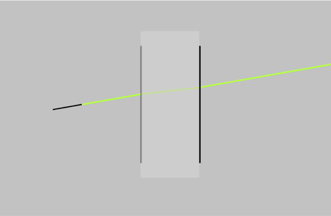
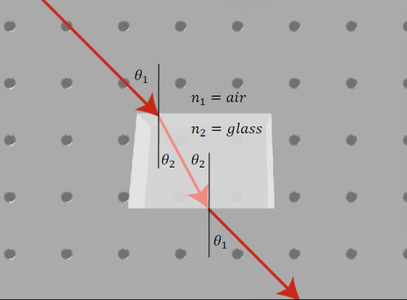
Exercise 2: Beam displacement using a tilted window/slab
  1. When a ray of light passes through a tilted glass window or a slab, it undergoes a displacement or shift in its path. This displacement can be calculated using the principles of geometric optics. The amount of displacement depends on the angle of incidence of the incoming ray, thickness of the plate and the refractive index of the slab or window. If the window is tilted at an angle with respect to the incident ray, the ray will be refracted or bent as it passes through the window.
a. To calculate the displacement of the ray, we can use the following formula:
D=t \sin\theta\bigg(1-\dfrac{\cos\theta}{\sqrt{n^2-\sin^2\theta}}\bigg)
Where D is the displacement of the beam, t is the thickness of the window/slab, and \theta is the angle of incidence.
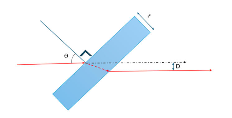
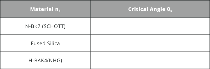
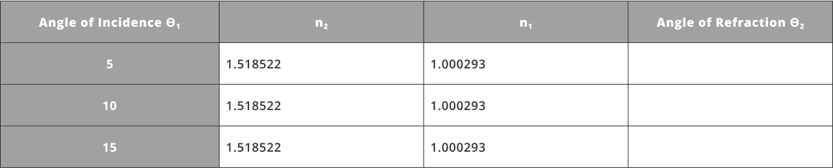
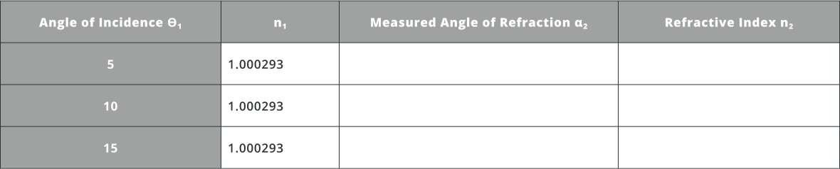
b. Calculate theoretically the displacement D with the parameters provided and fill the table below Refractive indexes of the material can be found under material properties, as shown in exercise 1.
  • Open the Analysis Portal and press Run Analysis.
  • Click on the detector window to enlarge it. Now position the cursor around the center of the beam and record the y coordinate as shown below.
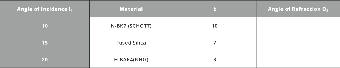
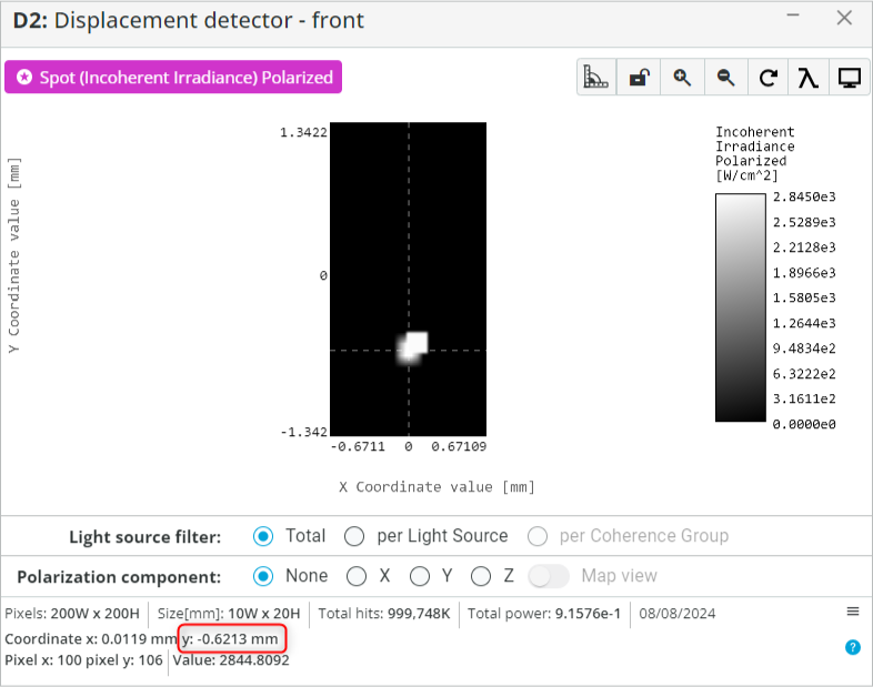
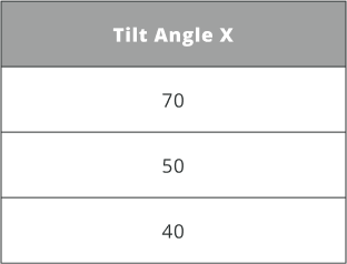
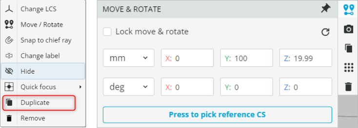
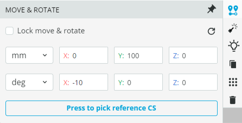
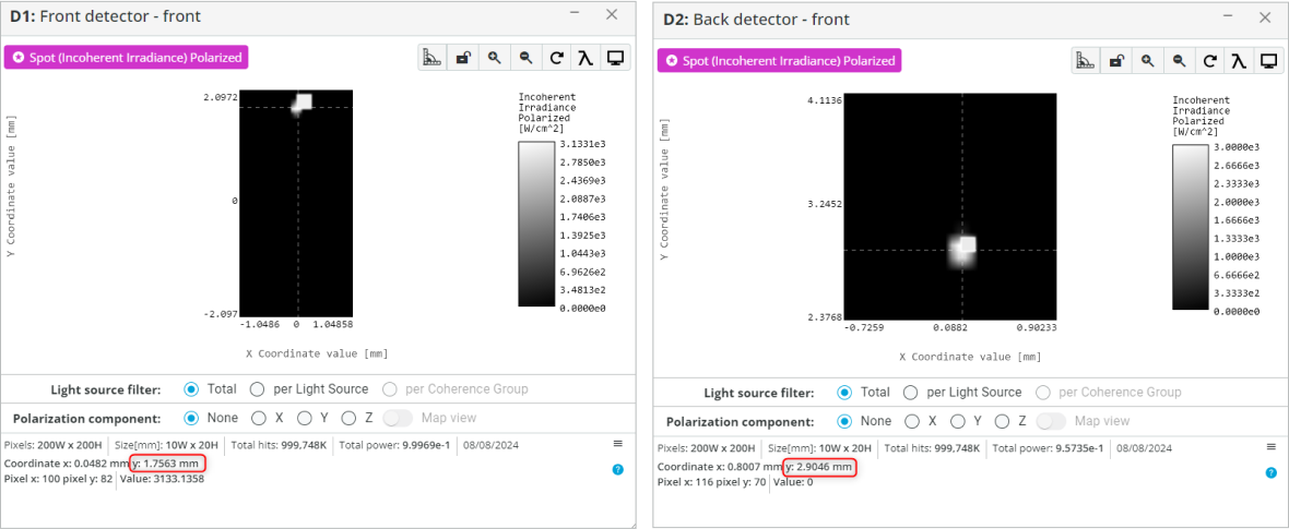
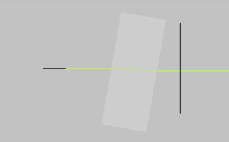
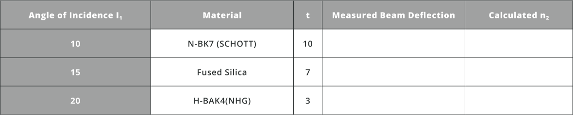
  • Change the material and angle of incidence (tilt angle) of the slab. Calculate the refractive index of the material using the beam deflection, incidence angle and slab thickness. Fill the table shown below Changing the tilt angle X and material is shown in exercise 1
Extra information
The technique of beam displacement using a tilted slab is essential in optical beam steering and alignment, particularly in laser systems and fiber optics. As light passes through a tilted transparent slab, it undergoes lateral displacement due to refraction, enabling precise control over the beam’s trajectory. In laser applications, where precise alignment is crucial for tasks such as cutting or communication, a tilted slab allows for fine adjustments in the beam’s direction without the need to move the entire apparatus. This method is especially useful in environments where mechanical movement is constrained or stability is critical, like in compact or vibration-sensitive settings. In fiber optics, where accurate alignment of the laser beam with the fiber core is key for effective light coupling, the tilted slab can be employed to shift the beam laterally, ensuring optimal alignment and minimizing signal loss.
Experiment 2

Total Internal Reflection

Transmission through an interface is often accompanied by a partial reflection. When light travels from a high refractive index material into a low refractive index material, the angle of refraction can become larger than the angle of incidence. If the refraction angle exceeds 90 degrees, no light can transmit from the high-index material into the low-index material. Thus, all the light is reflected back in a similar way to a perfect mirror. This is known as total internal reflection, and it happens whenever Snell’s law leads to:
\dfrac{n_1}{n_2}\sin(\theta_1)>1
In that case \sin(n_2) is larger than 1, which indicates that transmission is not physically possible. The smallest incident angle for which total internal reflection happens is when:
\dfrac{n_1}{n_2}\sin(\theta_1)=1
The incident angle θ_1 that produces an angle of refraction of 90ᵒ is called the critical angle, θ_c, and total internal reflection occurs for any incident angle greater than the critical angle, which is given by: 
\theta_c=(\dfrac{n_2}{n_1})
Where n_1 > n_2.
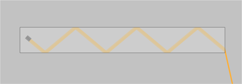
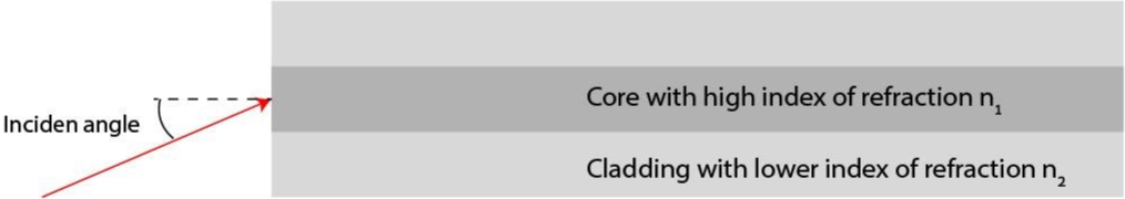
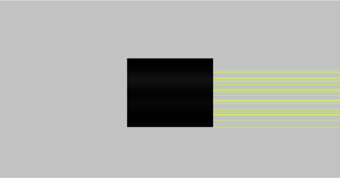
Exercise 3: Setting up a light source, a light pipe, a detector and calculating critical angle
  • Import the file “Ex_3_TIR_Start.opt” into the 3DOptix app. At this stage, only a light source is present. The light source properties can be accessed similarly to the process shown in exercise 1.
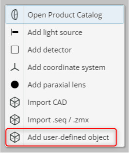
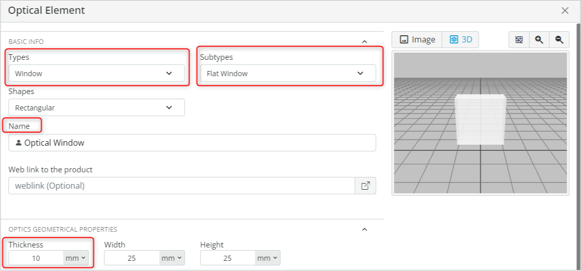
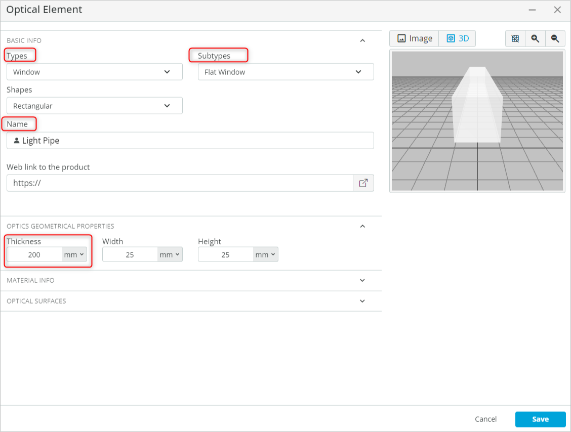
  • Add a light pipe to the scene. Right-click on the viewport background and select the User-defined object. This will open an Optical Element window. Add a flat window by performing the following tasks:
    • Under “BASIC INFO”, change the type to a “Window” and Subtype to “Flat Window”.
    • Change the name of the object to “Light Pipe”.
    • Change the thickness of the window to 200mm under Optics geometrical properties.
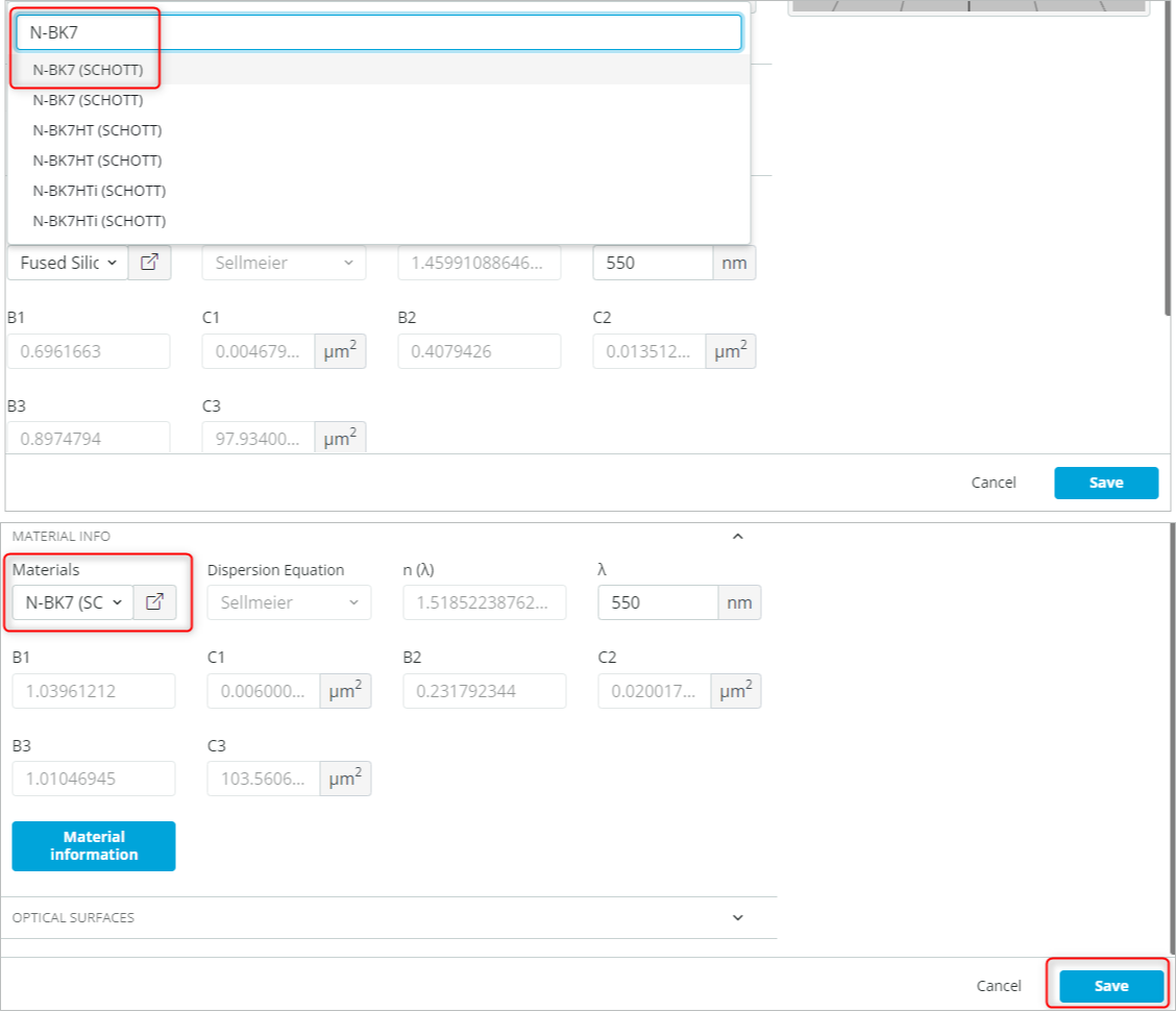
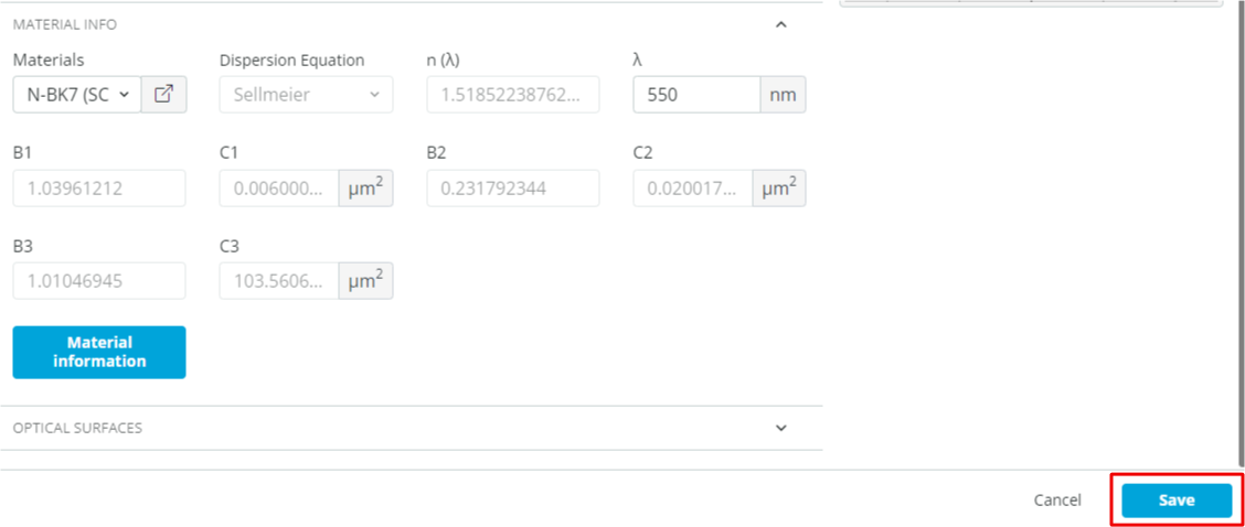
    • Change the material of the window under “Material info” to N-BK7 (SCHOTT). This is done by clicking the material and searching for the desired material.
    • Finally, click Save to add the object as shown below. Note: Refer to Exercise 1 on how to perform the given task.
  • Position the Light Pipe at the given coordinates as shown below.
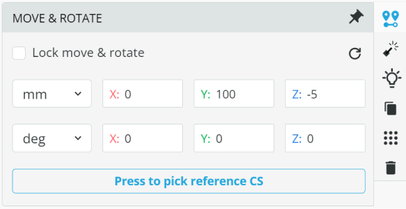
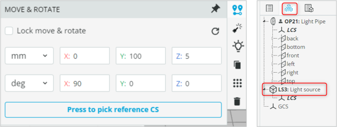
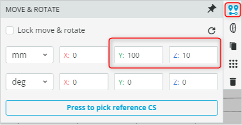
  • Put the light source inside the light pipe by positioning the Light source at the following coordinates. Note: If you are unable to access the light source, then use the Options/Settings available on the left-hand side to select the light source and then change the coordinates.
  • Click Propagation Simulation. The system should look similar to the one shown below
  • Calculate the critical angle and fill the table below. Assume n_2=1.000293
  • Change the tilt angle X for the light source as specified in the table below and observe the output.
    • Click Propagation Simulation each time the value of the tilt angle is changed.
    • The light will bend away from the normal as you change the angle from 70 to 50.
    • At an angle greater than \theta_c all the light will be reflected back, as shown below.
Extra information
The benefit of total internal reflection is that all the light is reflected without any losses. This contrasts with mirrors, which always have some losses. Therefore, total internal reflection is used in fiber optics for the transmission of information across vast distances. A fiber optics cable is composed of a core with a high index of refraction surrounded by cladding with a lower index of refraction. This is illustrated in Fig. 3, where we show the core made from one type of glass surrounded by the cladding, which is made from a different type of glass. Here, the index of refraction of the core is n_1 and the index of refraction of the cladding is n_2 and they must satisfy n_1 > n_2.
Fig. 3. Schematic of an optical fiber.
Optical fibers are designed to support only small incident angles. Therefore, the index of refraction difference between the core and the cladding is small, so only beams with a small incident angle can travel. If the core index of refraction is n_1 and the cladding is n_2, then the maximum angle of incidence which will propagate in the fiber is: 
\theta_{inc} \leq \dfrac{1}{n_0}\sqrt{n_1^2-n_2^2}
There are more considerations for a light beam to travel in optical fiber when the core is small enough. There must be constructive interference between two beams of light traveling in opposite incident angles. Thus, the light propagating from one side of the core to the other must equal an integer number of the wavelength. This leads to the number of modes that each fiber can support. However, all this will be discussed when considering the wave property of light beams and solving the propagation of electromagnetic fields in optical fibers.
Analysis and Conclusion
The refraction of light, Snell’s Law and total internal reflection are fundamental principles in the study of optics and have a wide range of practical applications. This course has equipped you with the knowledge and skills to comprehend, analyze, and manipulate the behavior of light when it encounters different materials and interfaces, paving the way for further exploration and application of these principles in the world of optics and photonics.
References:
NA
Assessment
NA
Resources
The student requires an account in the 3DOptix system.
Synopsys
This course delves into the fascinating world of light as it interacts with different materials. The student explores the fundamental principles of light when it passes and exits through a material, including an essential phenomenon governing the behavior of light when it encounters boundaries between different optical media. Through a series of experiments and exercises, the student gains a deep understanding of these optical phenomena and their practical applications.
mascot-1-1

3DOptix works
only on desktop!

Please go to 3doptix.com on a
desktop device, using the
Chrome or Edge browser

Available on January 30th, 2023