Introduction
Lensmaker's equation

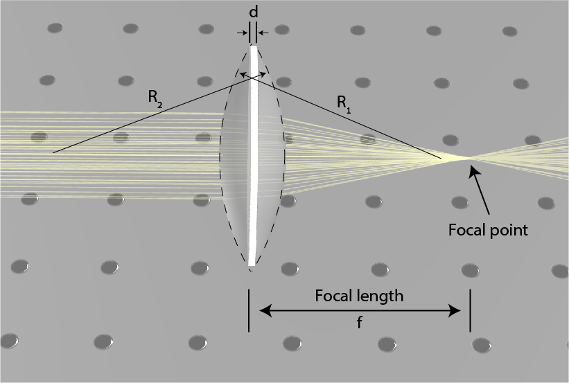
f1=(n−1)(R11−R21+nR1R2(n−1)d)
f1=(n−1)(R11−R21)
Types of lenses
In the lens presented in Fig. 1, the first radius is positive and the second one is negative, leading to a positive focal distance. However, the radius can have other radius value, including infinite. An infinite radius is in fact, a simple planar facet, whereas a negative first radius or positive second radius denotes as a concave facet. This leads to the possibility of a negative focal length.
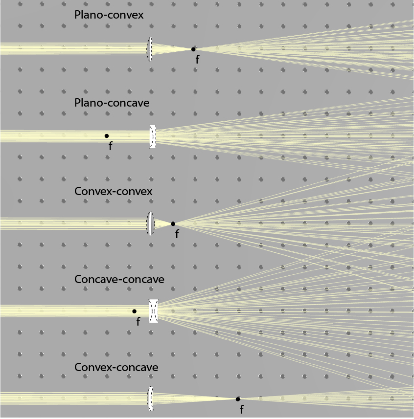
While a positive focal length indicates a focusing lens, in which a collimated beam is focused to the focal point, a negative focal length indicates a diverging lens in which a collimated beam diverges as if it came from the focal point. By setting the radius of each facet, we obtain five types of spherical lenses: plano-convex, plano-concave, convex-convex (or bi-convex), concave-concave (or bi-concave), and concave-convex. These five types of lenses are illustrated in Fig. 2 together with their focal point. Positive lenses are focusing light and have a positive focal length, negative lenses are diverging light and have a negative focal length, and concave-convex can do either, depending on which facet has higher curvature. In a concave-convex lens, if the convex facet has higher curvature than the concave facet, the lens is focusing, while if the concave facet has higher curvature, the lens is dispersing. When the two facets have identical curvatures, the focal distance will be infinite, meaning that the lens will not change the direction of light.

Exercise 1:
Load the file “Lenses_ex1.opt” and run the simulation (press the button below to download the file).
- Identify the focal length and measure the distance from the focal point to the lens.
- Click on the lens and enter “optical setting” then press the setting icon. Here you can change the curvature radiuses of the lens. Change the radiuses according the the table below, and run the simulations. Measure the focal length and fill in the following table:
| R1 | R2 | Measured f | Calculated f |
| 36 | -36 | ||
| 40 | -40 | ||
| 40 | -1000 | ||
| 40 | 80 | ||
| 20 | 40 |
|
|
| 20 | 20 |
f-number and the depth of focus
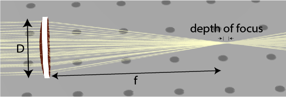
f#=Df

Imaging
f1=u1+v1

M=uv

Exercise 2:
Load the file: “Lenses_ex2.opt” (press the button below to download the file). In this file, two point sources serve as the input image. The two sources are separated by 5 mm.
- Identify the image plane. This is the plane where all the beams are focused into two spots. These two spots are the image of the two point sources.
- Measure the distance between the sources and the lens and the distance between the image and the lens and compare them and find the focal length of the lens.
- Measure the magnification of the image by measuring the distance between the two image-focused points. Compare this result to the calculated magnification.
- Move the sources so the magnification of the system will be M=10.
- Measure the magnification as a function of the distance from the lens. Fill in the following table:
| Distance from the focal length | Distance from the lens | Distance to the image | Magnification |
| 10 mm | |||
| 5 mm | |||
| 2 mm | |||
| 0 mm | |||
Imaging with two lenses

Telescopes have a similar 4-f system, but telescopes are intended to see faint far-away objects. Therefore, the first lens is large to collect a large amount of light, and the second lens is small to make far-away objects much closer.
Exercise 3:
Load the file “Lenses_ex3.opt” with its two lenses (press the button below to download the file). One lens has a focal length of 63 mm and the other has a focal length of 630 mm.
- Place the two lenses and the sources so the magnification will be M=10.
- Shift one of the lenses by 1 mm. What happens to the image if the lenses are not correctly placed? Shift the other lens. Did you observe a larger or smaller change?
| Distance from the focal length | Distance from the lens | Distance to the image | Magnification |
| 10 mm | |||
| 5 mm | |||
| 2 mm | |||
| 0 mm | |||


