Prisms

VIRTUAL LAB

Prisms

Course Overview
This pre-lab assignment aims to introduce students to the principles of prisms. Students will use 3DOptix, a virtual optical simulator, to explore different types of prisms and their properties.
Course Duration
Approximately 1-2 hours (self-paced)
Learning Objectives
By the end of this pre-lab assignment, students will have:
  • Gained an understanding of the concept of prisms, including their geometry and properties
  • Learned how prisms refract and disperse light, leading to the formation of spectra
  • Explored practical applications of prisms in science, photography, and optical devices
  • Learned the use of total internal reflection in prisms.
Course Outline - Introduction to Polarization
A prism is a transparent solid object with flat, polished surfaces that refract light. It is a geometric shape typically comprised of two parallel and congruent polygonal bases connected by a set of rectangular faces. The most common shape of a prism is a triangular prism, which has two triangular bases and three rectangular faces.
When light passes through a prism, it is refracted or bent as it travels through the prism. The refraction angle is determined by the medium’s index of refraction coefficient, which is the ratio between the speed of light in vacuum and the speed of light in the medium. Due to the fact that the refractive index is wavelength dependent, each color is bent at a different angle, and the light is separated into its component colors, creating a rainbow-like spectrum of colors. This phenomenon is called dispersion, and it is the reason why prisms are commonly used in optics to split white light into its individual colors.
Prisms have many practical applications, including in scientific experiments, photography, and optical devices such as binoculars, telescopes, and microscopes.
In this class, we will explore prisms, their underlying principles, various types, and their wide-ranging applications. We will understand how prisms work, the advantages they offer over other techniques, and the remarkable contributions they make to scientific discovery and technological innovation.

Prism Types

There are a variety of prism geometries, and 3DOptix offers support for many common types, including right-angle prisms, equilateral dispersion prisms, Dove prisms, Rhomboid prisms, Pellin-Broca prisms, and Penta prisms. These prisms are distinguished by their polygonal 2D shapes and a height parameter. Additionally, there are other prism types, such as axicon prisms and wedge prisms, which are commonly circular-based.

Each type of prism has its own unique characteristics and applications:

  1. Right Angle Prisms: These prisms have two perpendicular faces, and they are commonly used to deviate a beam of light by 90/180 degrees. They’re used in various optical systems, such as periscopes, binoculars, and range finders. They can also be used to combine or separate beams of light.
  2. Equilateral Dispersion Prisms: These prisms are triangular in shape, with three equal sides. They’re specifically designed to disperse light into its component wavelengths, making them crucial components in spectroscopy, optical instruments, and scientific experiments involving the analysis of light.
  3. Dove Prism: Shaped like a dove’s wing, these prisms have two non-parallel and equal inclined faces separated by a perpendicular face. They’re used to invert an image or change its orientation without rotating the optical system. They find applications in surveying instruments, range finders, and alignment systems.
  4. Rhombo-Prism: Also known as rhomboid prisms, these prisms have parallelogram-shaped faces. They’re used for beam steering and displacement applications where precise angular adjustments are required. They’re also used in laser systems and optical communications.
  5. Pellin-Broca Prisms: These prisms consist of two prisms cemented together at their hypotenuse faces, forming a cube. They’re primarily used for image rotation and inversion in optical systems, especially in ophthalmic devices, endoscopes, and imaging systems.
  6. Penta Prisms: These prisms have a five-sided polygonal shape with two mutually perpendicular faces. They’re used to reflect a beam of light by exactly 90 degrees without inverting or reversing the image. Penta prisms are commonly used in periscopes, surveying instruments, and cameras to maintain the orientation of the image.

Additionally, there are other prism types:

  • Axicon Prism: This prism has a conical shape, with one face flat and the other forming a cone. It’s used to generate a ring-shaped beam or focus light into a line. Axicon prisms find applications in laser processing, microscopy, and optical trapping.
  • Wedge Prisms: These prisms have two non-parallel, wedge-shaped faces. They’re used to deviate light by a specific angle or to introduce a controlled amount of angular dispersion. Wedge prisms are commonly used in laser systems, interferometry, and alignment setups in optical instruments.

Deviation of Rays and Color Dispersion

The deviation of a ray passing through a prism refers to the angle by which the ray is deflected or bent as it passes through the prism. This angle is determined by the refractive index of the prism and the angle of incidence of the incoming ray.

When a ray of light enters a prism at an angle, the ray is refracted toward the surface normal, which is perpendicular to the entrance surface of the prism. As the ray passes through the prism, it is refracted again at the other surfaces till it exits the prism.

The amount of deviation of the ray depends on the angle of incidence, the refractive index of the prism, and the prism’s geometrical shape. The deviation of a ray passing through a prism can be calculated using Snell’s law of refraction, which states that the ratio of the sines of the angles of incidence and refraction is equal to the ratio of the refractive indices of the two media. By applying Snell’s law, one can determine the angle of refraction and the deviation of the ray as it passes through the prism.

Experiment 1

Creating and Testing Polarization States

In this part, the student will derive the deviation of an incident beam entering a prism with an index of refraction n and a heading angle. In the derivation, we utilize the Snell law in each of the interacting surfaces. The ray schematics is shown in Fig. 1. Then the student will compare the calculated angle deviation with the measure simulation results.

Fig. 1. Ray schematics of the deviations of a ray of light from a triangular prism.
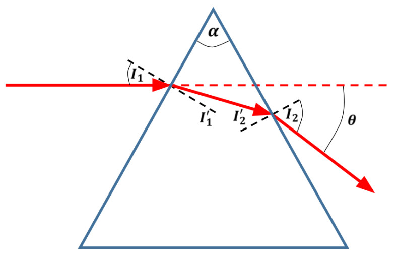
Exercise 1: Theoretical derivation of the beam’s deviation angle
Follow the following steps to derive the deviation angle \theta as a function of the input angle I_{1} and the prism angle \alpha :
  • The relation between the incident beam and the beam inside the prism is: \sin(I^{\prime}_1) = {\frac{1}{n}}\sin(I_1)
  • The relation between the angle on one surface compare to the angle on the other surface is: I^{\prime}_2 = \alpha – I^{\prime}_1
  • The relation between the beam inside the prism and the angle of the beam outside of the prism is: \sin(I_2) = n\sin(I^{\prime}_2)
  • Show the deviation angle \theta as a function of the input angle I_{1} and the prism angle \alpha, and show that it is:
    \theta = I_1 – \alpha + \arcsin \left((n^2 – I_1)^{\frac{1}{2}}\sin(\alpha) – \cos(\alpha)\sin(I_1) \right)
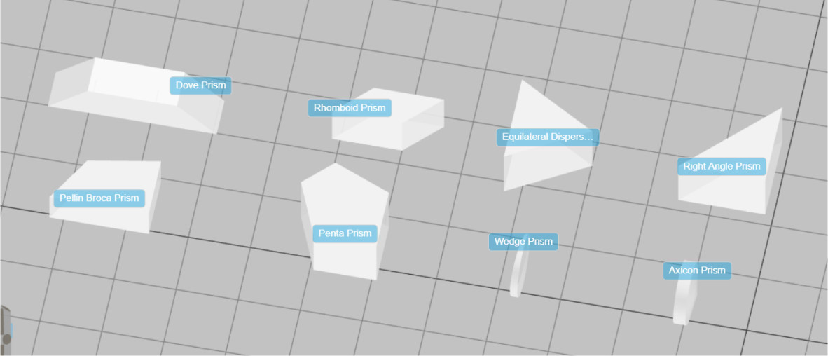
Exercise 2: Equilateral Dispersion Prism
  • The system is set up to measure the deflections of the broadband light source.

    The orientation angle of the prism will be varied to change the deflection angles. We start with the orientation Y angle of 165 deg.
  • The wavelengths of the light source are spanning 400nm to 700nm, with 25nm intervals.
  • There are two reference detectors (detector-front) that are locked to maintain the deflection of the beam. The detectors are placed at the outgoing beam to allow the calculation of the deviation of the rays. The global location of the detector can be viewed in MOVE&ROTATE panel.
  • Choose the Display type to be Spectral view.
  • Press the Wavelengths and select only the 400nm (blue) and the 700nm (red).
  • Find the location of the center of the beams for each of the colors.
  • You can click in the center of the image to bring up the cross-section view that can be used for the current and upcoming analyses.
  • You can alternatively measure only one of the colors (say 700nm) and use the distance measurement capabilities.
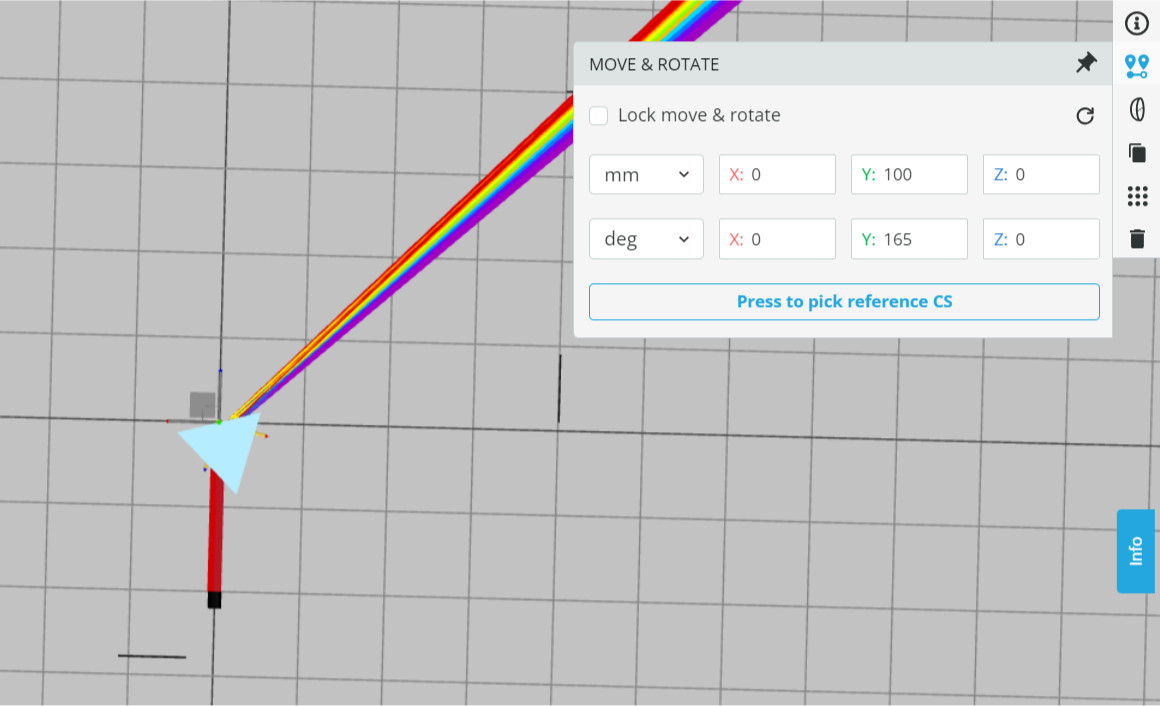
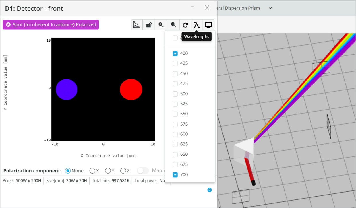
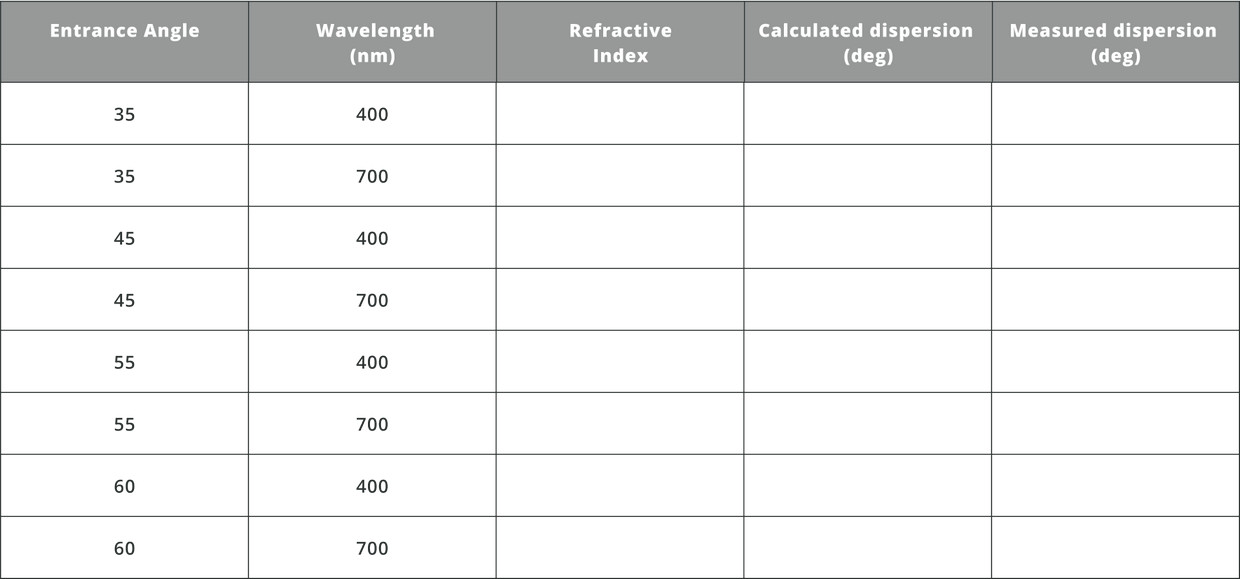
  • Rotate the prism and fill the following table with both experimental and calculated results for both λ=400nm and λ=700nm, and compare the measured angle to the calculated angle: There is a polarizer inserted into the optical path to change the amount of lighRemember that in Equilateral Prism the head angle is \alpha = 60^\circ. 
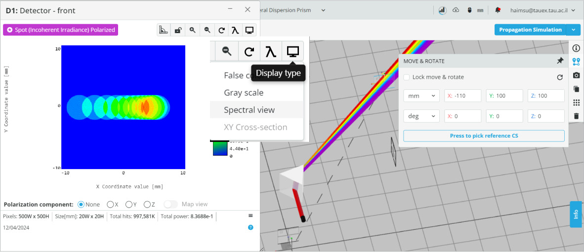
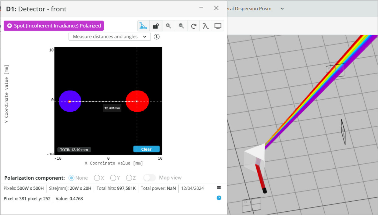
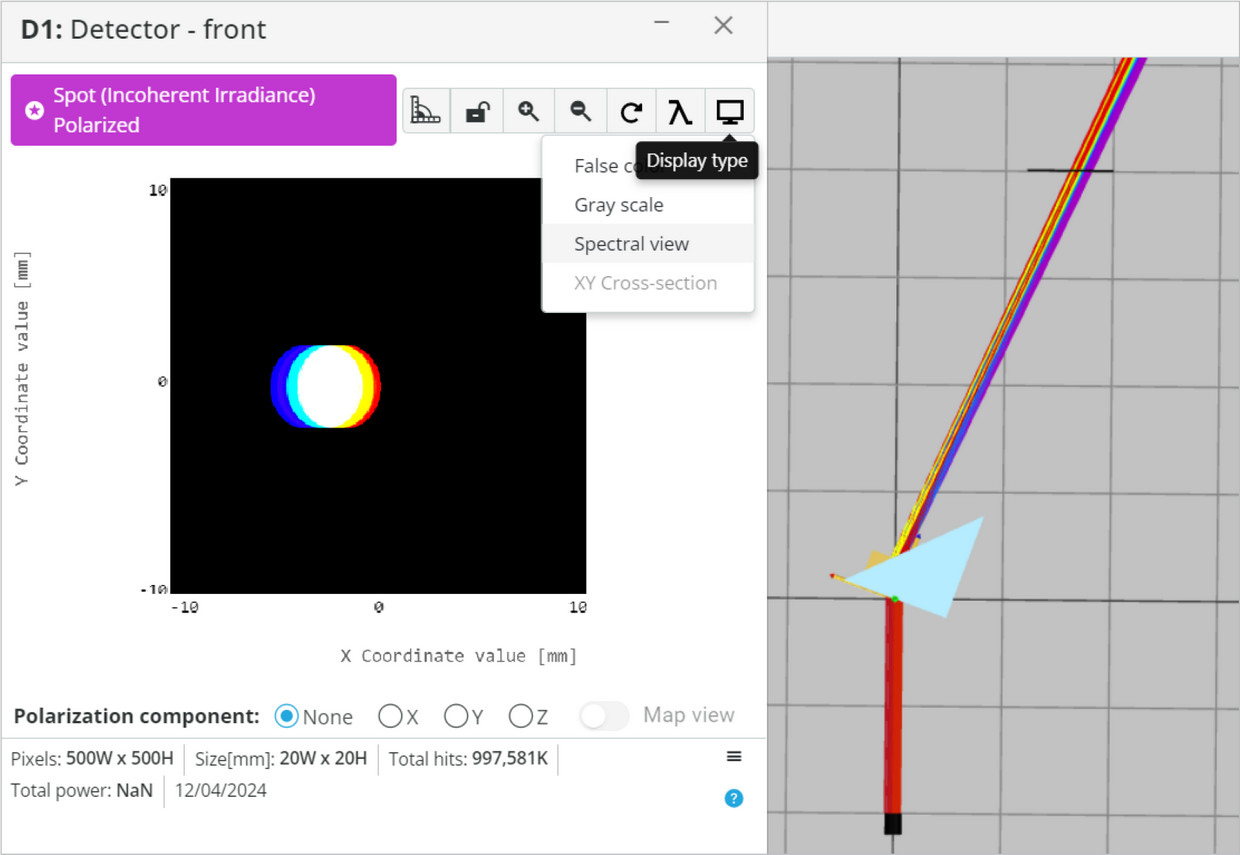
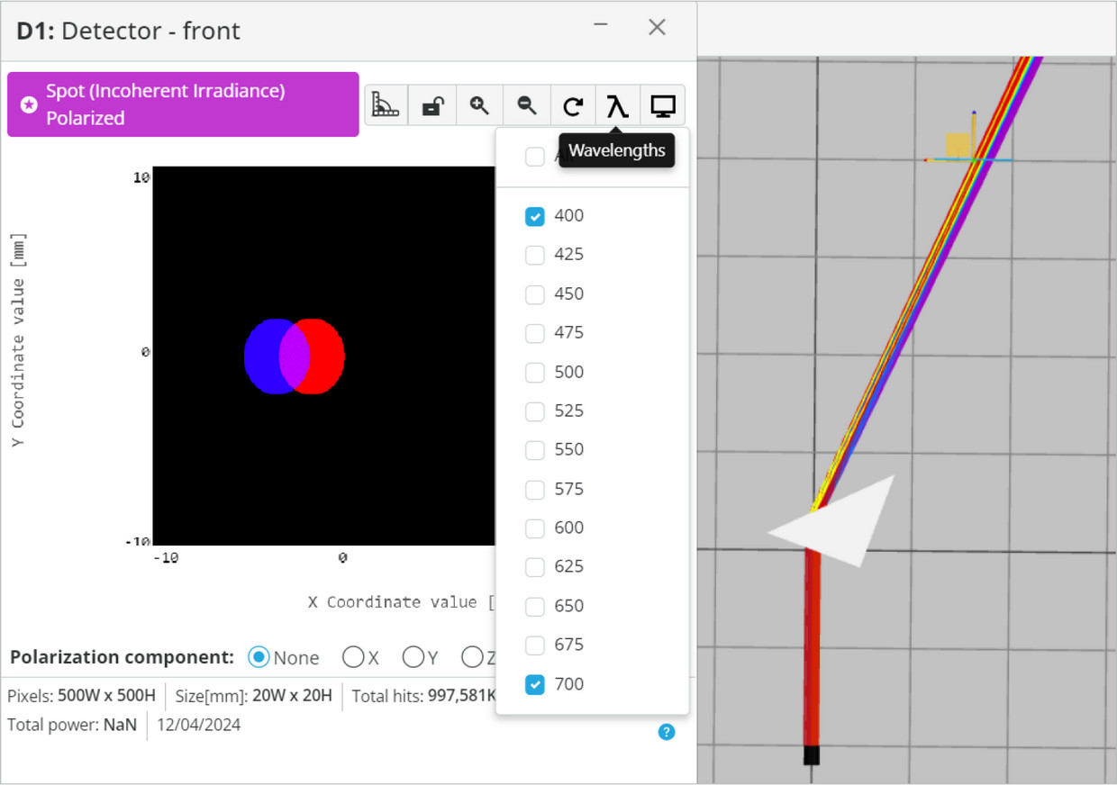
You should calculate the outgoing angles by finding the center of each color on the outgoing detector. Remember that all the colors enter in the same location and orientation.
  • We will now evaluate the dispersion of different wavelengths from a prism.
  • Differentiate the Eq. (1) as a function of n, and show that the change in D for a small change in n is: dD=\frac{I^{\prime}_2(\tan(I_1)+\sin(I_2))}{\cos(I_2)}
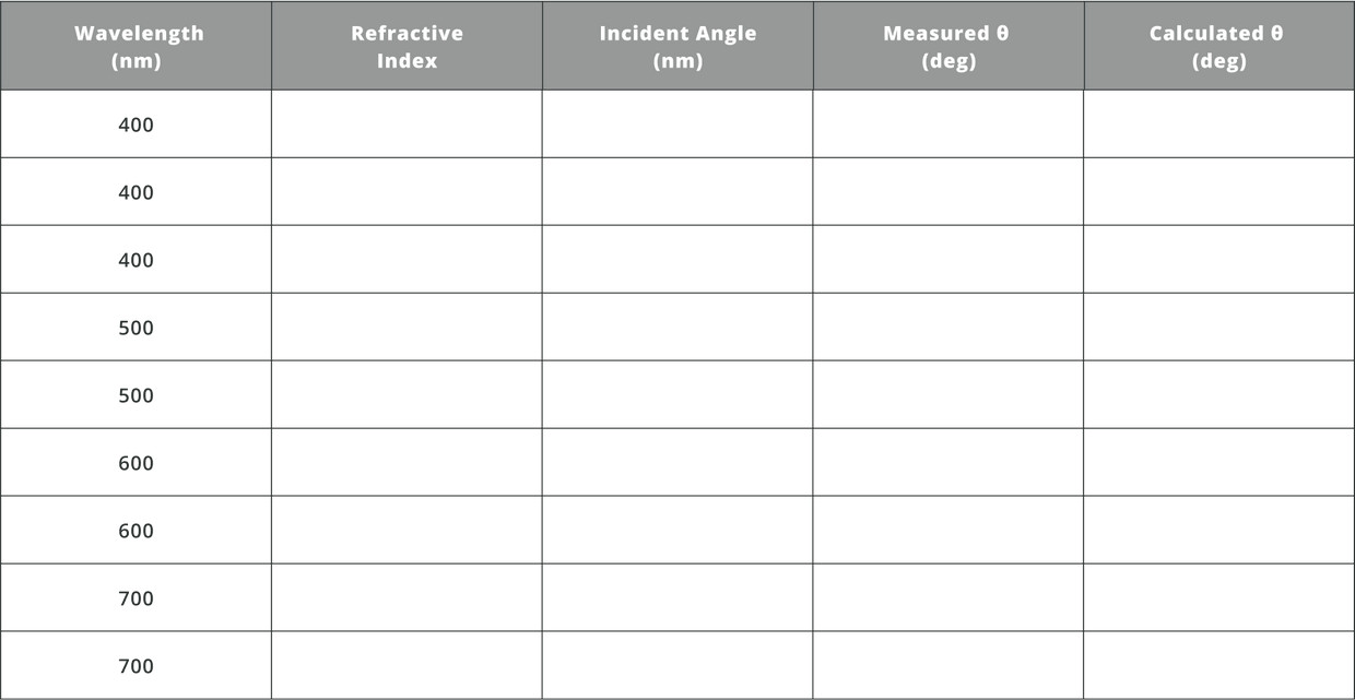
  • Fill the following table and evaluate the dispersion as a function of the input angle. First find the refractive index of each wavelength. You can calculate the dispersion angle from the distance measured from the blue color to the red color.
Experiment 2

Right Angle Prism – Dispersion and Total Internal Reflection

  • The system is set up for studying the transition between the deflections toward the total internal reflection of the broadband light source. We start with an orientation angle Y of the prism with 20 deg. The orientation angle will be varied to change the deflection angles.
  • Choose the Display type to be Spectral view
  • Click on Wavelengths and select only the 400nm (blue) and the 700nm (red).
  • You may move the Prism element in order to observe the trajectories of the colors inside the Prism, as shown in the following figure:
  • Once you are done, you can press the Undo button to place back the prism.
  • Rotate the prism to an orientation angle Y of 0 degrees. Press Run Simulation. What do you observe?
  • Can you explain the observation?
  • The phenomenon occurs due to the total internal reflection effect, which occurs when the light hits the surface inside an optical medium at an angle that is above the critical angle.
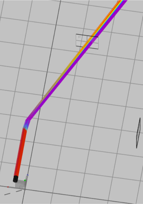
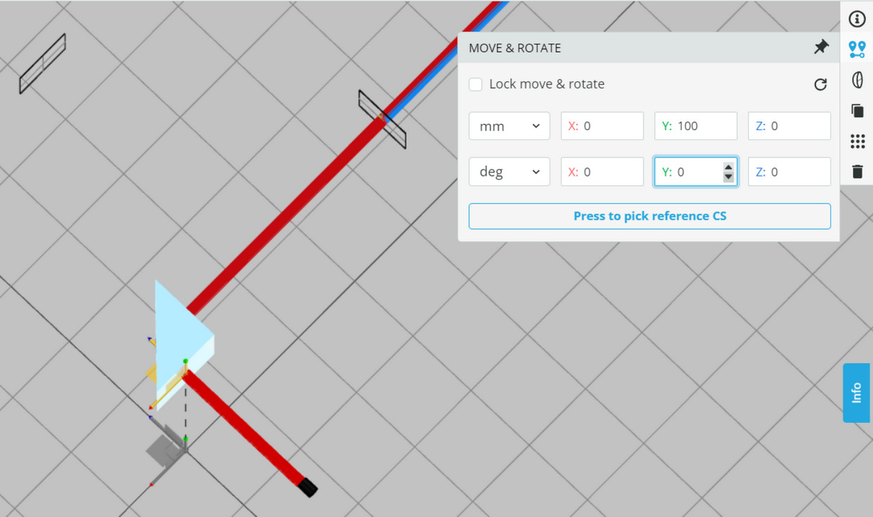
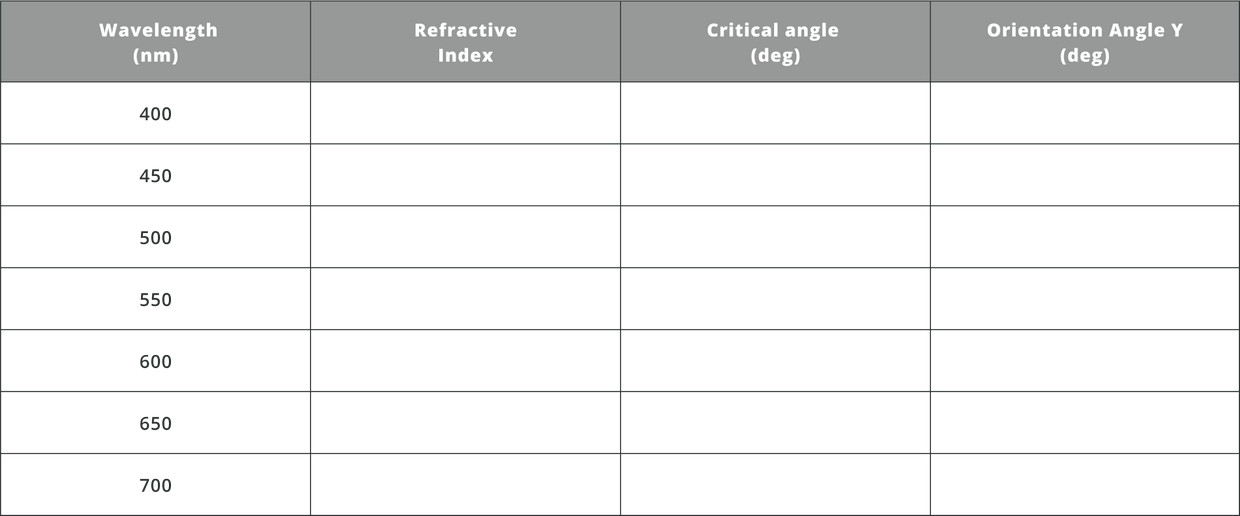
  • Fill the following table and evaluate the critical angle for the different wavelengths in a N-BK7 material First find the refractive index of each wavelength 
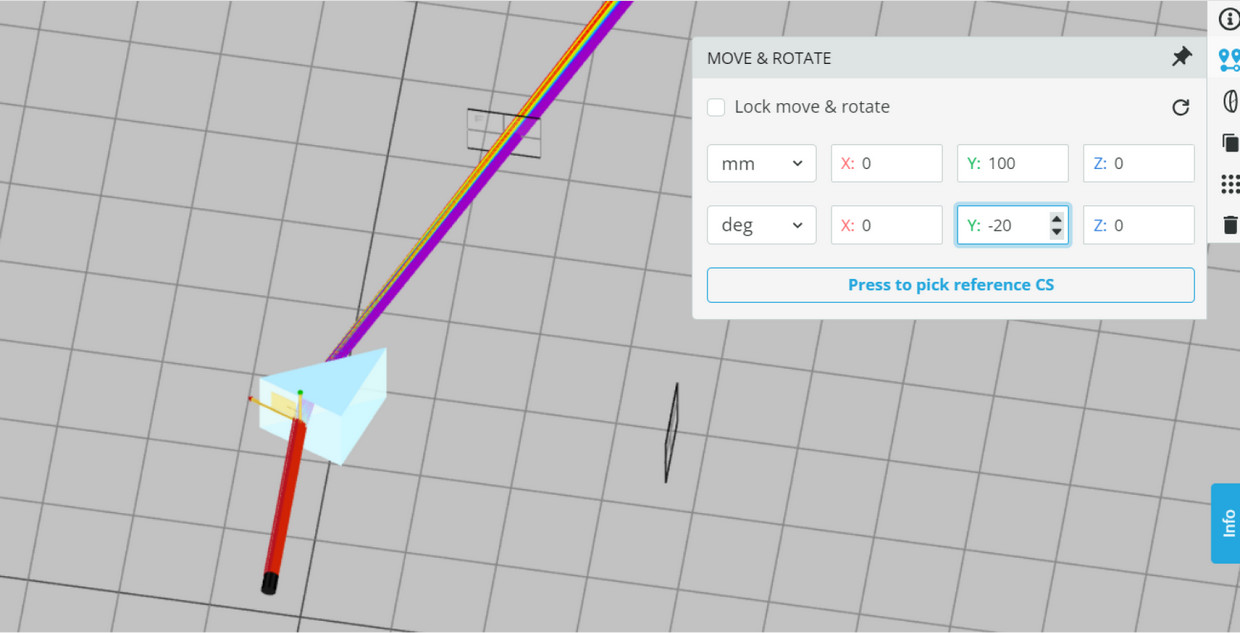
Rotate the orientation angle Y to observe the critical angle for each wavelength. Have you received the same angle as the critical angle? Can you explain why?
  • Rotate the Prism to orientation angle Y of 135 degrees. Press Run Simulation. What do you observe?
  • Can you explain the observation?
  • Such an effect is very useful and is being used as a retroreflector that transmits light back exactly 180 degrees.
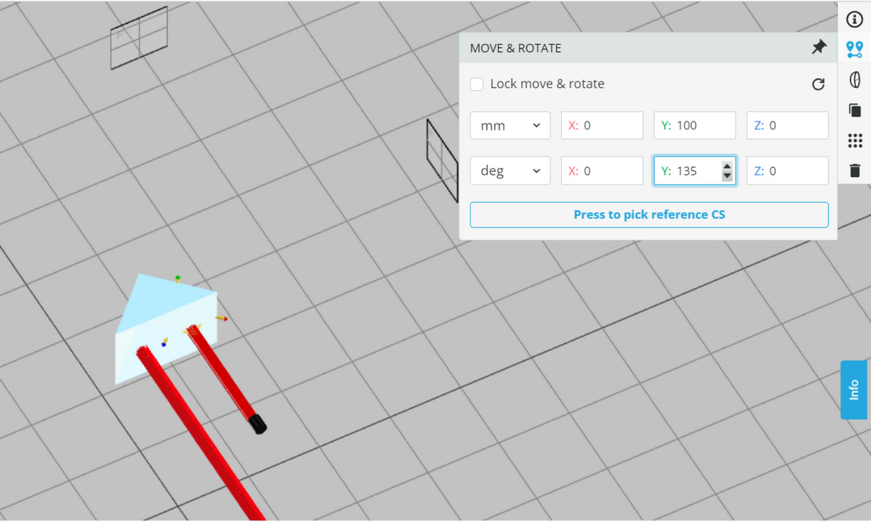
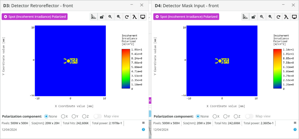
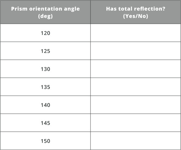
  • Fill the following table and evaluate the working angles of retroreflectors. Rotate the prism’s orientation Y angle  and determine the working angles of the retroreflector. Was it symmetrical relative to the center angle? Why?
Extra information on application of retroreflectors:

Retroreflectors have numerous applications across various fields. Some notable applications include:

  1. Traffic Safety: Retroreflectors are commonly used in road signs, lane markers, and vehicle license plates to enhance visibility for drivers, especially in low-light conditions or at night. These retroreflective materials bounce light back to the source (such as a vehicle’s headlights), making the signs and markers highly visible.
  2. Surveying and Alignment: Retroreflectors are used in surveying equipment, such as total stations and surveying prisms, to precisely measure distances and angles. By bouncing a laser beam off a retroreflector, surveyors can accurately determine positions and perform land surveying tasks with high precision.
  3. Spacecraft Tracking: Retroreflectors placed on satellites or other spacecraft serve as passive targets for laser ranging and tracking systems. By precisely measuring the time it takes for a laser beam to travel to the spacecraft and back, scientists can determine its position and orbit with high accuracy.
  4. Geodesy and Geophysics: Retroreflectors placed on the Moon during lunar missions, such as those left by the Apollo astronauts, are used for lunar laser ranging experiments. These retroreflectors allow scientists to measure the distance between the Earth and the Moon with exceptional precision, providing valuable data for studying Earth-Moon dynamics and testing theories of gravity.
  5. Photography and Imaging: Retroreflective materials are used in photography and imaging applications, such as reflective photo backdrops and clothing for safety during nighttime photography or outdoor activities. They help redirect light back toward the camera, enhancing visibility and improving image quality.
  6. Augmented Reality: Retroreflective markers are used in augmented reality (AR) applications to track the movement and position of objects or users. By placing retroreflective markers on objects or wearable devices, AR systems can accurately detect their positions in 3D space, enabling immersive experiences and precise interaction with virtual elements.

These are just a few examples of the diverse applications of retroreflectors. Their ability to bounce light back to its source makes them valuable tools in various fields, ranging from transportation and construction to astronomy and advanced technologies.

Experiment 3

Mask Orientations in Various Prisms

  • The system is set up for studying the image reflection in various prism orientations.
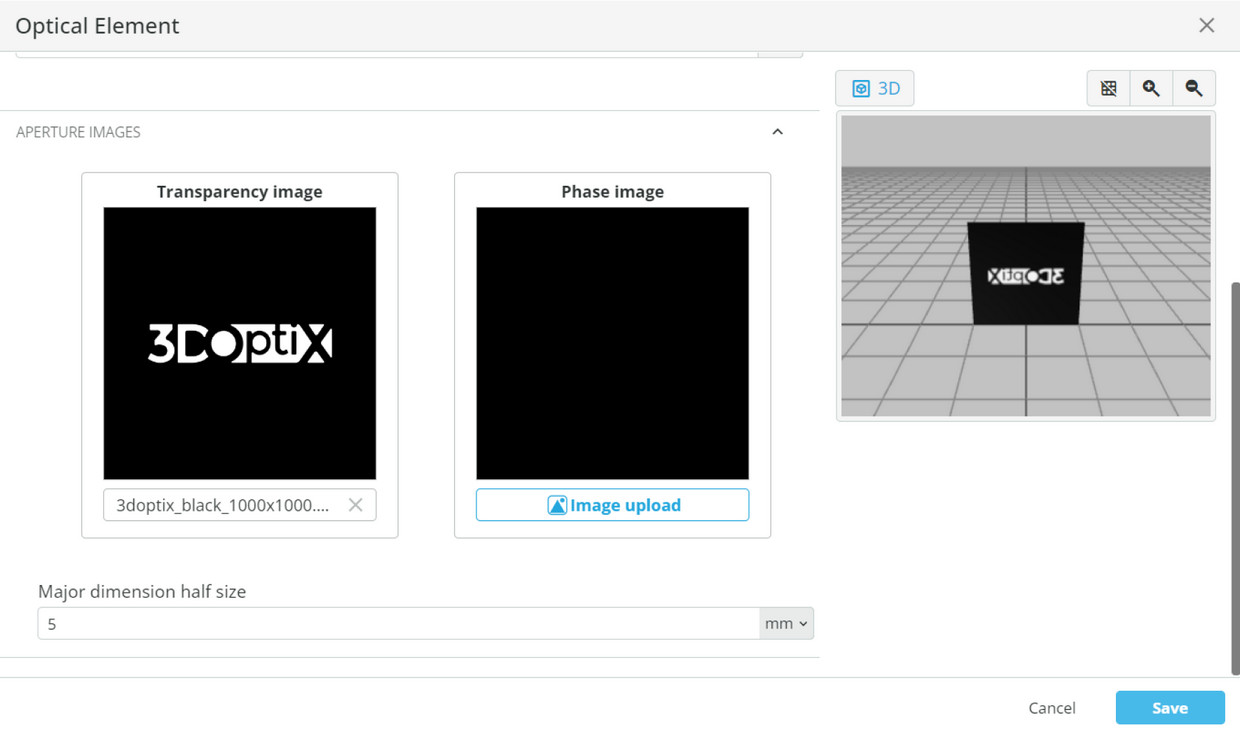
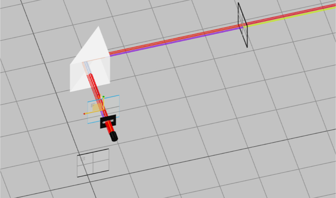
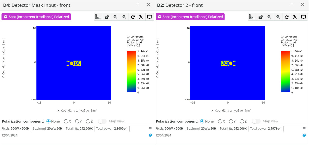
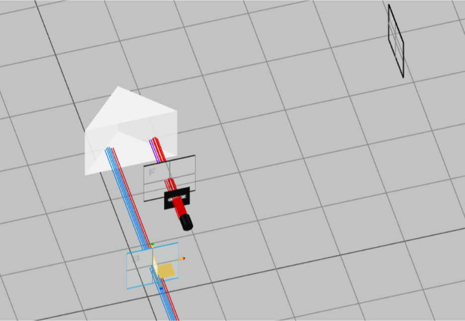
  • Verify that the Mask element contains the “3DOptix” mask. You can use any mask that you wish, yet in order to see the effect of the image reflection it is better to upload an image with X/Y orientations.
  • Run simulation.
  • Open the analysis portal and press Run Analysis. View the “Detector 2” output. Compare it to the “Detector Mask Input”.
  • Explain why the image was reversed.
  • Now change the Y orientation angle to 135 degrees and run the simulation again.
  • Open the analysis portal and press Run Analysis. View the “Detector Retroreflector” output. Compare it to the “Detector Mask Input”.
  • Explain why the image was not reversed in the current scenario.
Extra information

Prisms have played a crucial role in the history of optics and the understanding of light. From their early use in studying refraction to their modern applications in optical devices, telecommunications, and scientific research, prisms have been a fundamental component of optical technology and exploration. Prisms have been employed in various scientific and practical applications to study, manipulate, and utilize the properties of light. The use of prisms for studying the deviation of light dates back to the 17th century. Dutch scientist Willebrord Snellius (Snell) and French philosopher René Descartes made significant contributions to understanding the principles of refraction. Snell’s law, which describes how light rays change direction when passing through different media, laid the foundation for future work with prisms. Sir Isaac Newton conducted groundbreaking experiments with prisms in the late 17th century. He showed that white light could be separated into its component colors when passed through a prism, thus demonstrating the phenomenon of dispersion. Newton’s work on spectrum formation was instrumental in understanding the nature of light.

Throughout the 19th century, prisms were incorporated into various optical instruments. For example, prisms were used in sextants for navigation and spectrometers for chemical analysis. This era saw the development of precision-made prisms and optical devices. The 20th century brought significant advancements in optics and the use of prisms in various applications. Prisms were incorporated into cameras, binoculars, and other optical instruments. They are still widely used in photography, allowing the camera to focus and capture images. In the latter half of the 20th century, prisms found applications in fiber optics and telecommunications. Prisms were used for signal routing, wavelength selection, and dispersion compensation in optical communication systems.

Analysis and Conclusion
Throughout this virtual lab on prisms, students have gained valuable insights into the principles of prisms and parallel plates. The experiments conducted using a virtual optical simulator have allowed students to explore different types of prisms and understand how they operate.
Assessment
NA
Resources
The student requires an account in the 3DOptix system.
Synopsys
This course provides a comprehensive understanding of the fundamentals of prisms and their applications for various optical phenomena, strongly emphasizing hands-on virtual experiments and practical applications. Students taking this course can expect to gain a solid foundation in using prisms in optics and optical instrumentation.
mascot-1-1

3DOptix works
only on desktop!

Please go to 3doptix.com on a
desktop device, using the
Chrome or Edge browser

Available on January 30th, 2023