Introduction
Optical anamorphic systems are used to compress or expand the aspect ratio of images in photography and filmmaking. Anamorphic lenses use a special optical design that compresses the image horizontally while expanding it vertically, allowing for wider images to be captured on standard film or sensors.
In traditional filmmaking, anamorphic lenses were used to create a wide-screen cinematic look, which is now commonly referred to as “scope” or “widescreen”. The wider aspect ratio allows for a more immersive viewing experience, with more of the scene visible on the screen. Anamorphic lenses can also be used in still photography to create a similar widescreen effect. They are commonly used in landscape and architectural photography to capture a wider field of view. Anamorphic lenses can be expensive and require precise calibration, but their unique optical properties make them highly desirable for certain types of photography and filmmaking. They can produce a distinct and cinematic look that is difficult to replicate with other lenses.
There are several benefits to using anamorphic lenses in photography and filmmaking:
- Wider Field of View: Anamorphic lenses allow for a wider aspect ratio, which can capture a wider field of view. This makes them ideal for capturing landscapes, architecture, and large groups of people or objects.
- Cinematic Look: Anamorphic lenses create a unique cinematic look that is difficult to replicate with other lenses. The horizontal flares, oval bokeh, and stretched highlights create a distinct visual style that is often associated with classic Hollywood movies.
- Shallow Depth of Field: Anamorphic lenses typically have a shallower depth of field than traditional lenses. This creates a more cinematic look, with a blurred background and a sharp foreground.
- Compression: Anamorphic lenses can compress the image horizontally while expanding it vertically. This allows for a wider image to be captured on standard film or sensors without the need for a larger camera.
- Versatility: Anamorphic lenses can be used in both photography and filmmaking, making them a versatile tool for visual storytelling.
Anamorphic lenses can also be used in microscopy to increase the resolution of the microscope image in one direction. By using an anamorphic lens, it is possible to increase the resolution in one direction without compromising the resolution in the other direction. In microscopy, anamorphic lenses are typically combined with other lenses, such as objective lenses, to create a high-quality image. An anamorphic lens can be placed in front of the objective lens to stretch the image in one direction, allowing for a higher resolution in that direction. Anamorphic lenses are particularly useful in fluorescence microscopy, where they can be used to increase the resolution of fluorescent signals in a single plane. This can be especially helpful in live-cell imaging, where high-resolution imaging is essential to observe cellular processes. Also, anamorphic lenses can be utilized to obtain high-quality images with improved resolution, leading to a better understanding of biological processes at the cellular level.
Compressing and expanding in one axis
Diode lasers are a type of laser that uses a semiconductor material as the active medium to produce laser light. They are widely used in a variety of applications, including telecommunications, laser printing, laser surgery, barcode readers, and laser pointers. The basic structure of a diode laser consists of a p-n junction, where the p-type material has an excess of positively charged holes, and the n-type material has an excess of negatively charged electrons. When a voltage is applied to the diode, electrons are injected into the p-type material, creating a population inversion. This results in the emission of photons, which are confined to the active region of the diode by the use of mirrors. One of the advantages of diode lasers is their compact size, making them ideal for use in portable devices such as laser pointers or barcode scanners. They also have high efficiency, converting electrical energy to light with a high degree of efficiency. They can be operated at low currents and voltages, which reduces power consumption and heat generation. Diode lasers are also tunable, meaning their wavelength can be adjusted by changing the current or temperature. This makes them useful in telecommunications, where they can be used to transmit information over optical fibers.
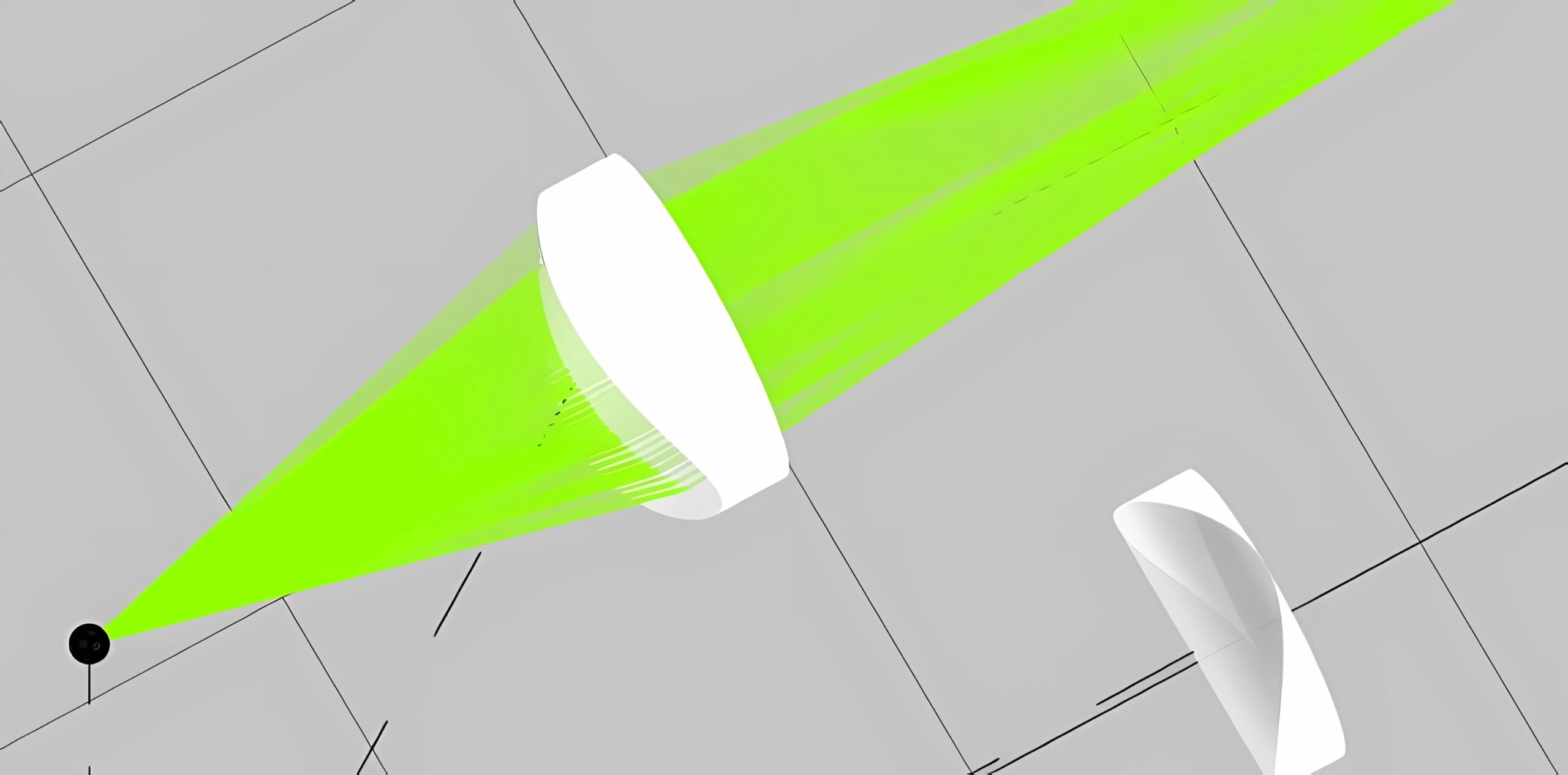
However, due to their asymmetric structure, the output beam is highly cylindrical, where on one axis, the beam expands faster than the other. This is due to the aspect ratios of the diode laser, where the width can be a few millimeters while the height is about a wavelength. Therefore, we resort to a cylindrical lens to obtain a collimated beam. The two cylindrical lenses should be placed in the correct positions to compensate for the asymmetric structure.
Exercise 1:
- Load the file “Anamorphic_ex1.opt” where we have a source with an angular divergence \theta of 10 degrees on the x-axis and 3 degrees on the y-axis. Run the simulation and observe the divergence of the beam.
- Convert the beam into a collimated beam with a width of D=14 mm in both directions. In order to do so, first set a cylindrical lens for collimating the x-axis. Calculate the correct focal length of the lens to reach this width by resorting to f=\frac{0.5\;D}{\tan\;(\theta/2)} . For obtaining the correct focal length, please find the radius of curvature of the first surface using the built in EFL calculator.
Open the calculator:
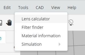
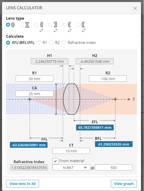
Choose the calculation mode of R1/R2, “Refractive index from material” mode as N-BK7 material, then, calculate the radius for the first cylindrical lens.
You should see the collimated X-direction beam after the first lens.

Place two detectors at different distances from first lens:

You can see that there is no change in the width of the spot on the detectors. This is an indication of collimation.

Define a detector with the size of 14X14 mm (Half-width and half high 7X7 mm). Find the axial position of the detector, when the spot is circular (not elliptic).

- There are two lenses that you can use and change their properties and positions. Set the correct lens diameter for obtaining this focal length and place the lens at the correct position. Run the simulation to verify that the beam is collimated in the x-axis.

- Repeat the same procedure on the y-axis and show that you can obtain a collimated beam with a diameter of 14 mm.
Next, you should use two anamorphic lenses to change the aspect ratio of images. Here, we need to design an imaging system with different magnitudes in both axes. The imaging condition is 1/u+1/v=1/f, where u is the distance between the lens and the object, v is the distance between the lens and the image, and f is the focal length of the lens. In a plano-convex lens, the focal length follows:f=R/(n-1), where R is the lens curvature, and n is the index of refraction. The magnification of such an imaging system is M=-v/u. When we design an imaging system with different aspect ratios, we use two anamorphic lenses, one for the x-axis and one for the y-axis. Therefore, we can define u_x and u_vfor the x axis, and u_y and v_y for the y-axis. The object and the image planes are identical for both axes, so: u_x+v_x=u_y+v_y=d , which sets the curvature of both lenses and their location.
- Load the file “Anamorphic_ex2.opt” where we have four point sources.
- Place a detector at a 200 mm distance from the sources.
- Design an imaging system with an X2 magnification at the x-axis, and an X1.5 magnification at the y-axis. Change the curvature radius accordingly and place the lenses at the correct location.
Prism-based anamorphic systems
Anamorphic systems can be designed using prisms, which are optical elements that are used to refract and reflect light. The basic concept behind using prisms to create an anamorphic system is to use a pair of prisms to stretch the image in one direction while compressing it in the perpendicular direction.

The compression as a function of the angle is:
D_{out}=D_{in} \cos (\sin^{-1}(\frac{\sin(\alpha-\sin^{-1}(\frac{1}{n}\sin(\frac{\alpha}{2})))}{n}))
Where, D_{in} is the width of the input beam, D_{out} is the width of the output beam, \theta is the deviation angle from the beam direction due to the prism, n is the index of refraction of the prism, and \alpha is the top angle of the prism. In the next exercise, the student will calculate the compression as a function of the angle of an equilateral prism compared to the incident beam.
Exercise 3:
- Load the file “Anamorphic_ex3.opt” and run the simulation
- Place a detector at the input beam and evaluate the beam diameter.
- Place a detector at the output beam and evaluate the beam diameter
- Fill in the following table:
| Prism angle | Beam diameter |
| 0 | |
| 10 | |
| 20 | |
| 30 | |
| 40 | |
| 50 | |
| 60 |
- Find an analytic expression for the output beam diameter as a function of the prism’s angle.
One way to create an anamorphic system using prisms is to use a pair of right-angle prisms. These prisms are arranged so that the hypotenuse of one prism is in contact with the adjacent side of the other prism. When light passes through this system, it is refracted and reflected, causing the image to be stretched in one direction and compressed in the perpendicular direction.

- Load the file “Anamorphic_ex4.opt” and run the simulation
- Place detectors before and after the prisms and evaluate the compression of the beam.
- Change the angle of the prisms and fill the following table:
| Prism angle | Compression |
| 85 | |
| 80 | |
| 70 | |
| 60 | |
| 50 | |
| 40 | |
- Find an analytic expression for the compression as a function of the prism angle and index of refraction.
Another way to create an anamorphic system using prisms is to use a pair of Dove prisms. Dove prisms have two reflecting surfaces at 90-degree angles to each other, which causes the light to be reflected on itself. By arranging a pair of Dove prisms with their reflective surfaces oriented at different angles, the image can be stretched in one direction while being compressed in the perpendicular direction.
Anamorphic systems made using prisms can be relatively compact and lightweight compared to other anamorphic systems, such as anamorphic lenses. They can also be less expensive, making them a good option for certain applications where cost and portability are important. However, anamorphic systems made using prisms can suffer from some limitations, such as image distortion and chromatic aberration. These issues can be addressed through careful design and calibration of the anamorphic system.
Overall, anamorphic systems made using prisms are a viable option for creating a stretched image in one direction while compressing it in the perpendicular direction. They offer a compact, lightweight, and cost-effective solution for certain applications, such as microscopy or machine vision.
