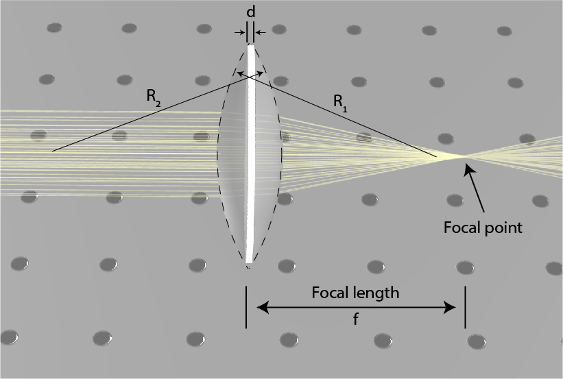
Lenses are usually made from two spherical or plane facets from a transparent material. The schematic of a convex-convex lens is illustrated in Fig. 1, together with its parameters and its influence on a collimated beam showing the focal point.
The radii of both facets, the width of the lens, and the index of refraction of the material determine the focal length of the lens according to the lensmaker’s equation:
Here n is the index of refraction, d denotes the width of the lens, R_1 is the radius of the first facet and R_2 is the radius of the second facet, as schematically shown in Fig 1. We define a radius from right to left with a positive value and a radius from left to right with a negative value. This equation is illustrated in Fig 1 where changing the radius of each facet, the width of the lens, and the material index of refraction, is influencing the focal length of the lens. In many cases, the lens is thin relative to the two radii, and in those cases, it is possible to simplify the equation to:
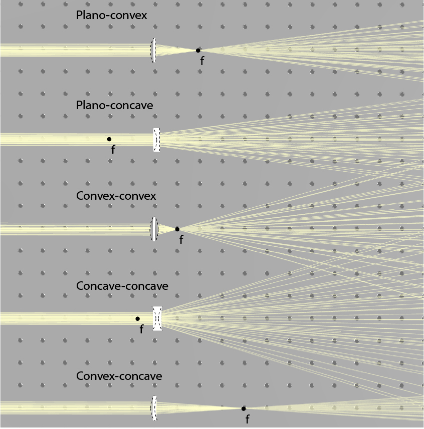
In the lens presented in Fig. 1, the first radius is positive and the second one is negative, leading to a positive focal distance. However, it is also possible to have other values for the radius including infinite. An infinite radius denotes a simple planar facet whereas a negative first radius or positive second radius denotes a concave facet. This leads to the possibility of a negative focal length. While a positive focal length indicates a focusing lens, in which a collimated beam is focused to the focal point, a negative focal length indicates a diverging lens in which a collimated beam diverges as if it came from the focal point. By setting the radius of each facet, we obtain five types of spherical lenses: plano-convex, plano-concave, convex-convex (or bi-convex), concave-concave (or bi-concave), and concave-convex. These five types of lenses are illustrated in Fig. 2 together with their focal point. Positive lenses are focusing light and have a positive focal length, negative lenses are diverging light and have a negative focal length, and concave-convex can do either, depending on which facet has higher curvature. In a concave-convex lens, if the two facets have identical curvatures, the focal distance will be infinite, meaning that the lens has no optical power, and it will not change the direction of light.
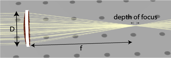
The f-number of a lens is a measure for the lens’ ability to focus light. The f-number is calculated by the focal length over the diameter of the lens, as:
Where f# denotes the f-number of the lens, and D denotes the aperture of the lens. As the f-number decreases, the lens can focus light into smaller spots. The depth of focus of a lens is the length along the optical axis where the beam is focused. As the f-number of the beam increases leading to a smaller spot, the depth of focus decreases, as illustrated in Fig. 3.
For example, for f-number of f#=1, the focal distance equals the lens aperture, leading to a spot size of the wavelength of the beam. However, when the spot size is small, the depth of focus is also short.
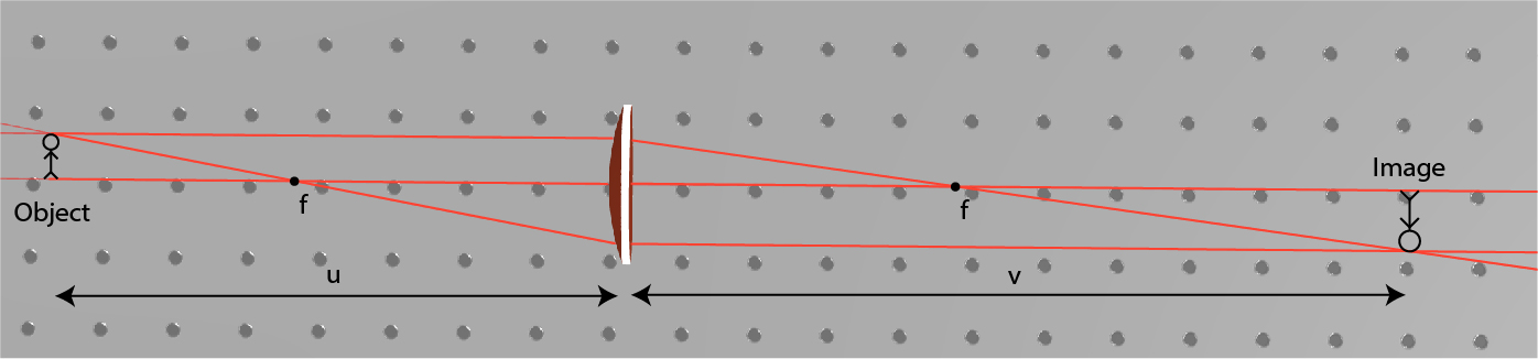
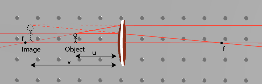
Once we have a lens, we can utilize it to image an object. We show schematics of an imaging system with a positive lens in Fig. 4. When an object is placed at a distance u from the lens, the image is generated at a distance v, according to:
A positive v indicates a real image, and negative v indicates an imaginary image. A real image is when there is a plane in space where the light distribution is similar to the object. By placing a screen in this plane we can observe the image. An imaginary image is when the light propagates as if there is such a plane. By looking into the beam, we see the imaginary image but we cannot place a screen in space to observe the image.
The magnification of the image, denoted as M, is set according to
For a positive lens, when the object is placed farther than the focal length from the lens, the lens generates a real image according to the Imaging Equation. This is illustrated in Fig. 4. This real image can be compressed or magnified, but it will always be inverted. If the object is farther than 2f from the lens, the image will be compressed, but if the object is placed between f and 2f, the image will be magnified. When we move the object closer to the focal length, we increase the magnification of the image. When we place the object between the focal length and the lens, the lens generates an imaginary image. The imaginary image is not inverted, it is magnified, and on the same size of the lens as the object is, this is illustrated in Fig. 5.
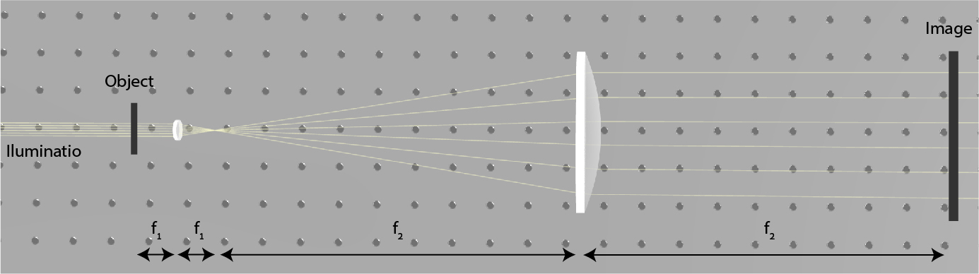
An imaging system that is based on a single lens has limited magnification since any lens has aberrations. When trying to fabricate stronger lenses, we also increase the aberrations. One way to overcome this drawback is to resort to an imaging system with multiple lenses. Multiple lenses can lead to an imaging system with high magnification where each lens by itself is not too strong. Many imaging systems are based on multiple lenses, including microscopes and telescopes. The basic optical setup in both cases is the 4f imaging system.
The 4-f imaging system is based on two lenses situated at a distance of their combined focal lengths one from the other. This is illustrated in Fig. 6. In microscopes, we place the object next to a small lens with a short focal length and a large lens is used for imaging the object to the image plane. The magnification is the relation between the focal lengths of the two lenses.
Telescopes have a similar 4-f system, but telescopes are intended to see faint far-away objects. Therefore, the first lens is large to collect a large amount of light, and the second lens is small to make far-away objects much closer.
Warehouse
Pricing
Company
