

Prisms are optical elements that are made from a bulk of transparent material and some of their faces are not parallel. Prisms are an important element and were used for diffracting light into its spectral components long before gratings were invented. Today, prisms are used for directing light by total internal reflection, deflecting light, diffraction of input beam into its spectral components, and for splitting into the different states of polarization.
When light passes from one transparent material to another it diffracts according to the Snell law. This diffraction follows:
If one of the materials is air, we can assume that n_1=1 and we are left with:
Here, we see that the angle depends on the index of refraction. Since the index of refraction depends on the wavelength: n_2(λ) we can get a different angle for each wavelength. This is called dispersion and leads to the dispersion of white light into all its components where each component travels in a different direction. Thus, the exit angle \alpha_2 is a function of the input wavelength, \alpha_2(\lambda). When looking at it we observe a rainbow of all the colors of the white beam.
This diffraction is used in many prisms which diffract different spectral components in different directions and is one of the main properties of a prism. We will describe here several prisms which are using this property to separate light into its spectral components but in different directions and different situations.
When increasing the angle inside the material \alpha_2 and since n_2>n_1 we can reach a situation where n_2\sin\;(\alpha_2)>1. In that case, there is no diffraction of light outside, there is no \alpha_1 which satisfies Snell law. Therefore, the light will not exit the material and will be reflected completely. This reflection is called total internal reflection and is utilized in many cases for directing images in different orientations and directions. This is the second main property of a prism. When a prism is used to direct light beams and images without losses.
Dispersive prisms are used for separating a beam of light into its spectral component where each component is directed in a different direction. There are different types of prisms and each prism is used in different systems.
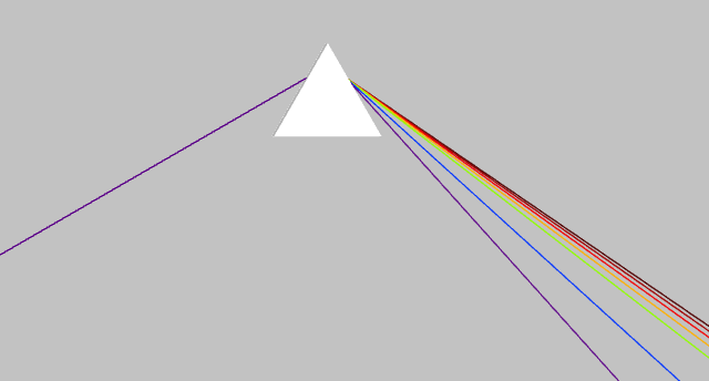
The most basic and known prism is the equilateral prism. It is composed of three identical facets with angles of 60 degrees between them. This prism is used for diffracting light into its spectral components at an angle that depends on the input wavelength. We present this in Fig. 1, where we can see how different wavelengths are reflected in different directions and the detector observes a rainbow.
There are prims which make it easier to design optical systems with dispersion. The main problem with an equilateral prism is that the diffraction angle is arbitrary. Some prisms are designed for 0 degrees, 60 degrees, or 90 degrees, which are more convenient. These are the Amici prism, the Abbe prism, and the Perlin-Boca prism.
The Amici prism is made from two prisms each from a different type of glass. The result is a beam that continues in the same direction it enters the prism for one specific wavelength. The prism is designed so the specific wavelength will be the central wavelength of the input beam. This is idle for measuring the spectrum of objects in telescopes and microscopes since the user can look at an object, and then enter the prism which will give the spectrum of the incoming light and the spectrum will be at the same position as the image.
The Abbe prism preserves an angle of 60 degrees compared to the input beam so the central wavelength is directed at 60 degrees and other wavelengths are directed slightly from this angle. The Perlin-Broca prism is similar only it directs the central wavelength at 90 degrees compared to the input beam. The Perlin-Borca prism ray schematics are shown in Fig. 2.
A grism is the combination of a prism with a grating. Light is entering the prism from one side and is diffracted downward. In the middle of the prism, there is a grating that diffracts the different components upward. This leads to diffracting the light again at the other facet where the central wavelength continues. This Grism is similar to the Amici prism and is used in the same situations. It can have larger diffraction than the Amici prism but it requires more complicated fabrication techniques.
These prisms are used for reflecting beams of light or images in a different direction, with or without change in the image. These prisms are based on total internal reflection which leads to high reflection efficiency. The only challenge is entering the prism without losses and this is possible with an anti-reflection coating.
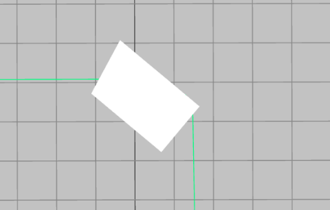
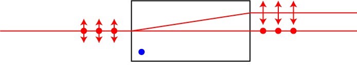
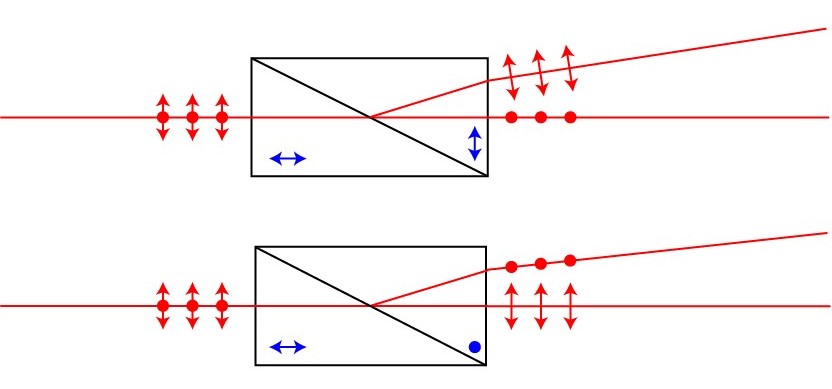
This prism is also one of the basic prisms. It has one angle of 90 degrees and two angles of 45 degrees. The total internal reflection angle of glass is 43 degrees, and therefore, when interacting with a facet that is 45 degrees, the light will be reflected. This prism can be used for redirecting a beam or an image at 90 degrees if entering one of the small facets. In this case, the image will be inverted by 90 degrees as shown in Fig. 3. When entering the prism from the long facet, the beam hits both small facets and reflect in the same direction it arrived from. When sending an image in this configuration, the image is inverted by 180 degrees.
There is also the option to enter the small facet at 45 degrees, as shown in Fig. 4. In this case the beam hits the bottom facet and exits in the same direction it entered but the image is inverted and reversed. This configuration does not use the upper part of the prism, and we can omit it which leads to a prism known as the Dove prism. There is also the Schmidt–Pechan prism which does not change the direction of the beams and the image but flips the image up and down and left and right, while the dove prism flips only up and down. The ray schematics of a Dove prism are shown in Fig 4.
The pentagon prism is a commonly used prism for cameras. This prism reflects light at 90 degrees compared to its input direction without inverting or reversing the image. The image remains the same only at 90 degrees compared to the input direction. The beam schematics in the prisms are shown in Fig. 5. It can be imitated with 3 mirrors, however, mirrors are not as robust as a prism, which remains aligned even in challenging conditions.
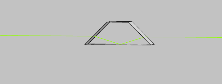
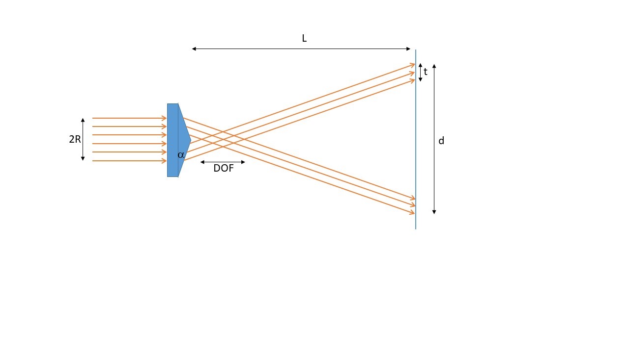
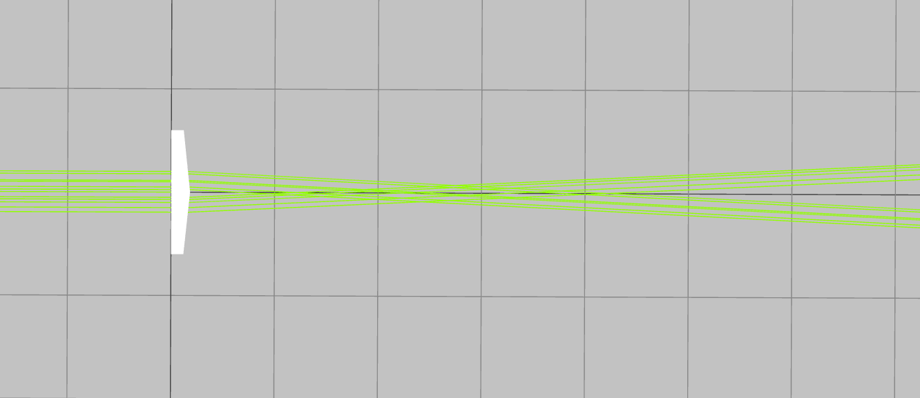
The effect of an axicon prism is similar to a lens. It directs a parallel beam of light into a focus, but, unlike a lens, the focus is a line and not a point. This is illustrated in Fig. 6. Therefore, the depth of focus of an axicon is especially long and is calculated by:
Where \alpha is the angle of the axicon, R is the width of the input beam, and n is the index of refraction.
Outside of the focus Axicon generates Bessel beams. Bessel beams are beams that are shaped like rings of light that do not diffract and preserve their shape as they propagate in space apart from changing size and phase. The width of the ring of light is calculated by:
Where, n is the index of refraction of the material,
Rhomboid prisms are not prisms by definition since their input and output surfaces are parallel to each other, they are similar to a tilted window. This type of prism is used to displace a beam of light without changing its angle with a small dependence on the input wavelength. All wavelengths travel at the same trajectory regardless of their effective index of refraction, however, the displacement is a function of the wavelength due to the material dispersion. The ray tracing scheme of a Rhomboid prism is shown in Fig. 7 demonstrating the displaced beam due to the prism.
All the prisms until now are made from isotropic material, meaning, the material has the same index of refraction regardless of the axis of the beam. There are materials with different indices of refraction for a specific axis. These materials are called birefringence materials, and the axis with the special index of refraction is called the extraordinary axis while the other two are called ordinary axes. These materials are usually crystals with some preferred axis or plastic under stress.
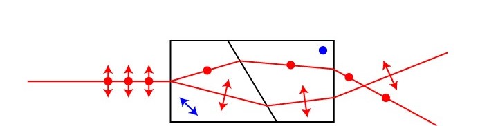
When light is traveling in such materials, it will interact with the material according to its polarization. Thus, one polarization may feel one index of refraction while the other will feel a different one. When the beam is traveling at an angle compared to the crystal axes, this can lead to a spatial separation between the two states of polarization, as seen in Fig. 8.
This property enables the design of prisms that act differently on each state of polarization and therefore can separate the two as a polarization beam splitter. A simple calcite crystal is not a good polarization beam splitter since the spatial separation is small, and for separating the two beams, we need a long crystal that has higher losses and is more complex to fabricate. In addition, the two states of polarization leave the crystal co-propagating and close to each other. A good beam splitter should separate the two beams in space so it will be easy to manipulate each one separately.
To obtain a good spatial separation, there are two main techniques. The first one resorts to combining different types and orientations of birefringence materials, each cut at a different angle, so the two beams will obtain an angular separation, meaning that each state of polarization will be directed in a different direction. The second technique resort to designing the angles of the prism such that one state of polarization will be reflected by total internal reflection while the other state will have high transmission thanks to the Brewster angle.
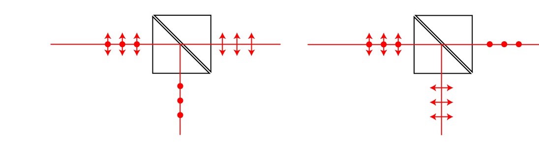
These prisms are based on combining two right-angle prisms made from calcite crystals. Each prism is fabricated by a calcite crystal with a different orientation. Therefore, when the beam hits the contact between the two prisms, each state of polarization is affected by a different index of refraction, and therefore, is directed toward a different direction. The angular separation of the two beams can be tuned by choosing the angle between the two prisms. Three examples of this type of polarization beam splitter are the Wollaston prism and the Rochon prism. The Wollaston prism directs the two beams equally compare to the optical axis, Rochon beams direct one state of polarization while the Senarmont prism directs the other state of polarization, as shown in Fig. 9.
These prisms are utilized the different indices of refraction of each state of polarization so one state of polarization will be reflected by total internal reflection while the other will transmit throw the prism. To improve the efficiency of the prism and the polarization purity of each beam, the prisms are designed so the incident angle is the Brewster angle. This is a specific angle where one state of polarization cannot reflect from a surface. These prisms can have higher efficiency than the previous type and the two states of polarization have higher angular separation. Examples of these types of prisms are the Nicol prism, Glan–Foucault prism, Glan–Taylor prism, and the Glan–Thompson prism. In Fig. 10 we present the ray tracing schemes of two such prisms.
A unique prism combines angular and spatial separations which leads to a useful interferometer for microscopy. This is the Nomaraski prism which is presented in Fig. 11. The benefit of this prism is that the two beams are focused outside of the prism where a detector or a sample can be placed.
Warehouse
Pricing
Company
