Snell’s law or the law of refraction describes the relation between the angle of incident of light to the angle of refraction. The first formulation for the relation between angles of refraction was formulated by Ptolemy, an ancient mathematician in Alexandria, Egypt. The relation was discovered and rediscovered several times during the centuries, and eventually was named after Dutch astronomer Willebrord Snellius (1580-1626) who in 1621 derived the relation but never published it during his life.
When light travels through transparent materials, it interacts with the atoms and molecules. The light is an electromagnetic wave so it excites oscillations in the charges in the materials similar to the oscillations of small floaters on water. Since the wavelength of the light is much larger than the size of the charges, the light senses the averaged effect over many charges. This interaction slows down the light, so the speed of light in a material depends on the material properties. We denote for each material a single number, known as the “index of refraction” which describes the interaction between light and the material. The index of refraction of the vacuum is 1 and a higher index of refractions indicates a slower light speed. For example, the index of refraction of water is about 1.3 and most types of glass have an index of refraction at around 1.5.
When light travels from one medium to another, it also changes its direction. The change in the direction of the light beam is related to the index of refraction according to:
Where, n_1 and n_2 are the indexes of refraction of the first and second material, respectively. This law is illustrated in Fig. 1, where we can see the input beam traveling in the air entering glass, and changing the direction of propagation according to Snell’s law.
When light interacts with a square piece of material, the light will exit at the same angle as it enters but will be shifted in space. The beam of light preserves its direction as long as the input and the output surfaces are parallel to each other. The light trajectory is displaced from its original trajectory and this displacement is a function of the index of refraction of the material. This is illustrated in Fig. 2.
One way to measure the index of refraction of materials is by sending a laser beam through a thick slab of the material. Next, we rotate the slab and measure the displacement of the laser beam as a function of the rotating angle. If the angle of the material is \alpha and the width of the material is d then, the displacement of the laser beam, \trianglex is obtained by:
Where all the parameters are presented in Fig. 3 and show the displacement of the beam from its original trajectory.
Although most of the light transmits through the transparent material, some of the light reflects back. When the light incident is perpendicular to the surface, the reflection coefficient is:
When the light beam is not perpendicular to the plane, there is a difference in the reflection between the two states of polarization. The state of polarization which oscillates parallel to the plane of incident is called “transverse electric” or TE and denoted as the P state of polarization, where the state When the light beam is not perpendicular to the plane, there is a difference in the reflection between the two states of polarization. The state of polarization which oscillates parallel to the plane of the incident is called “transverse electric” or TE and is denoted as the P state of polarization, whereas the state of polarization which oscillates in the other direction is called “transverse magnetic” or TM and denoted as the S state of polarization. We denote the reflectivity amplitudes of the P and S polarizations as, r_p and r_s, respectively, and the transmission amplitudes as t_p and t_s. The relations between the transmission or reflection amplitudes, and the incident angle are:
Transmission through an interface is often accompanied by a partial reflection. When light is traveling from a high refractive index material into a low refractive index material the angle of refraction is larger than the angle of incidence. If the reflection angle exceeds 90 degrees, no light can transmit from the low-index material into the high-index material. Thus, all the light is reflected back similar to a perfect mirror. This is known as total internal reflection, and it happens whenever Snell’s law leads to:
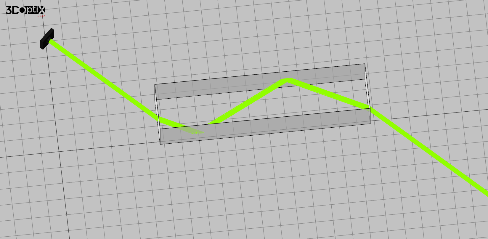
In that case \sin(\theta_1) is larger than 1 which indicates that transmission is not physically possible. The smallest incident angle for which total internal reflection happens is when \frac{n_2}{n_1}\sin(\theta_2)=1. This total internal reflection is demonstrated in Fig. 5, where we simulate a beam traveling in a long piece of glass from one side to the other.
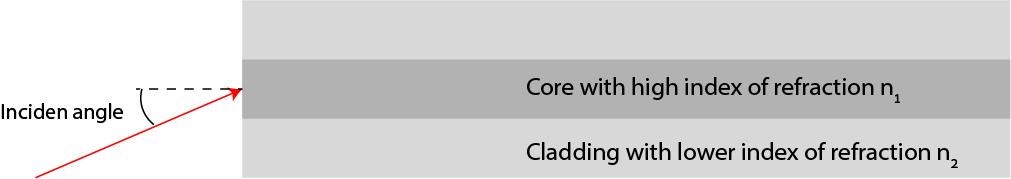
The benefit of total internal reflection is that all the light is reflected without any losses. This is in contrast to mirrors which always have some losses. Therefore, total internal reflection is used in fiber optics for the transmission of information across vast distances. A fiber optics cable is composed of a core with a high index of refraction surrounded by cladding with a lower index of refraction. This is illustrated in Fig. 6, where we show the core made from one type of glass surrounded by the cladding which is made from a different type of glass. Here, the index of refraction of the core is n_1 and the index of refraction of the cladding is n_2 and they must satisfy n_1>n_2.
Optical fibers are designed to support only small incident angles. Therefore, the index of refraction difference between the core and the cladding is small so only beams with a small incident angle can travel. If the core index of refraction is n_1 and the cladding is n_2, then the maximum angle of incidence which will propagate in the fiber is:
There are more considerations for a light beam to travel in optical fiber when the core is small enough. There must be constructive interference between two beams of light traveling in opposite incident angles. Thus, the light propagating from one side of the core to the other must equal an integer number of the wavelength. This leads to the number of modes that each fiber can support. However, all this will be discussed when considering the wave property of light beams and solving the propagation of electromagnetic fields in optical fibers.
Warehouse
Pricing
Company
