Introduction
A prism is a transparent solid object with flat, polished surfaces that refract light. It is a geometric shape typically comprised of two parallel and congruent polygonal bases connected by a set of rectangular faces. The most common shape of a prism is a triangular prism, which has two triangular bases and three rectangular faces.
When light passes through a prism, it is refracted or bent as it travels through the prism due to the change in the speed of light as it enters a new medium. This causes the light to separate into its component colors, creating a rainbow-like spectrum of colors. This phenomenon is called dispersion, and it is the reason why prisms are commonly used in optics to split white light into its individual colors.
Prisms have many practical applications, including in scientific experiments, photography, and optical devices such as binoculars, telescopes, and microscopes.
Deviation of rays
The deviation of a ray passing through a prism refers to the angle by which the ray is deflected or bent as it passes through the prism. This angle is determined by the refractive index of the prism and the angle of incidence of the incoming ray.
When a ray of light enters a prism at an angle, due to the change in speed of light as it enters a new medium, the ray is refracted towards the surface’s normal, which is the imaginary line perpendicular to the surface of the prism. As the ray passes through the prism, it is refracted again at the opposite surface and exits the prism at a slightly different angle.
The amount of deviation of the ray depends on the angle of incidence, the refractive index of the prism, and the angle of the prism. The deviation is minimum when the angle of incidence is zero and maximum when the angle of incidence is equal to the critical angle of the prism.
The deviation of a ray passing through a prism can be calculated using Snell’s law of refraction, which states that the ratio of the sines of the angles of incidence and refraction is equal to the ratio of the refractive indices of the two media. By applying Snell’s law, we can determine the angle of refraction and the deviation of the ray as it passes through the prism.
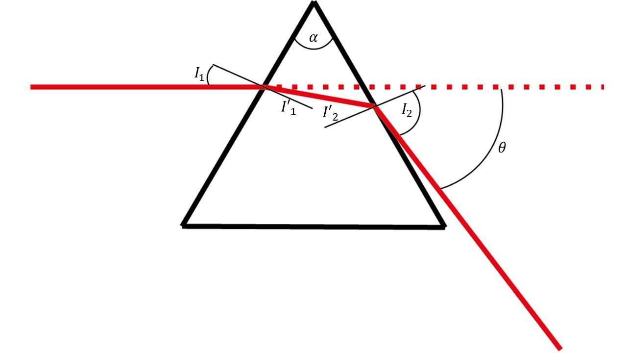
Calculating the deviation of an incident beam, denoted as D, from a prism with angle is calculated by following the Snell law from each surface. The ray schematics is shown in Fig. 1.
Exercise 1:
Derive the deviation of the beam from a prism with an index of refraction n.
- The relation between the incident beam and the beam inside the prism is:
\sin(I’_1)=\frac1n\sin(I_1)
- The relation between the angle on one surface compare to the angle on the other surface is:
I’_2=\alpha-I_1
- The relation between the beam inside the prism and the angle of the beam outside of the prism is:
\sin(I_2)\;=\;n\sin(I_2)
- Derive the deviation angle D as a function of the input angle I1 and the prism angle and show that it is:
\theta\;=\;I_1-\alpha\;+\;arc\sin({(n^2-\sin^2I_1)}^\frac12\;\sin\alpha\;-\;\cos\;\alpha\;\sin\;I_1)
- Load the file “prism_ex1.opt” and run the simulation (press the button below to download the file).
- Place two detectors at the outgoing beam and calculate the deviation of the ray.
- Rotate the prism and fill the following table with both experimental and calculated results. The index of refraction is 1.52 and α=60°.
| Incident angle | Measured theta | Calculated theta |
| 30 mm | ||
| 35 mm | ||
| 40 mm | ||
| 45 mm | ||
- Change the wavelength and measure and calculate the deviation
| Wavelength [nm] | Index of refraction | Measured theta | Calculated theta |
| 400 | 1.53 | ||
| 500 | 1.521 | ||
| 600 | 1.516 | ||
| 700 | 1.513 | ||
| 800 | 1.51 |
Use the same method to calculate the angle deviation of a beam from a right angled prism rotated at 25 degrees. Load the file “prism_ex1b.opt” (press the button below to download the file) , run the simulation and check your calculation.
- Differentiate the equation in 4 as a function of n, and show that the change in D for small change in n is:
dD=\frac{(\cos I’_2\;\tan\;I’_1\;+\:\sin\;I’_2)}{\cos\;I_2}\\
- Add several colors in the light source and check the dispersion as a function of input angle.
| Wavelength [nm] | Index of refraction | Dispersion |
| 400 | 1.53 | |
| 500 | 1.521 | |
| 600 | 1.516 | |
| 700 | 1.513 | |
| 800 | 1.51 |
Plane parallel plate
When a ray of light passes through a tilted glass window, it undergoes a displacement or shift in its path due to the change in the angle of the window. This displacement can be calculated using the principles of geometric optics.
The amount of displacement depends on the angle of incidence of the incoming ray and the angle of the window. If the window is tilted at an angle with respect to the incident ray, the ray will be refracted or bent as it passes through the window. The amount of refraction depends on the refractive index of the glass and the angle of incidence of the ray.
To calculate the displacement of the ray, we can use the formula:
D\;=\;t\;\sin\;I_1\left(1-\sqrt{\frac{1-\sin^2I_1}{n^2-\sin^2I_1}}\right)\\

Where d is the displacement of the ray, t is the thickness of the glass, and theta is the angle of the window. This formula assumes that the angle of incidence is small, and the glass is thin compared to the distance traveled by the ray.
If the angle of incidence is not small or the glass is thick, we need to use more complex formulas that take into account the variation of the refractive index with wavelength and the thickness of the glass.
It is important to note that the displacement of the ray due to a tilted glass window can cause errors in the measurement of distances or angles in optical systems, and it needs to be taken into account in the design and calibration of such systems.
Exercise 2:
- Load the file “prism_ex2.opt” (press the button below to download the file), run the simulations
- There are 5 different windows of width of 10 mm on the setup. Take each window and measure the displacement of the beam as a function of the angle. From these measured results you can calculate the index of refraction of each window. Please fill the following table.
| Incident angle | Displacement window 1 | Displacement window 2 | Displacement window 3 | Displacement window 4 | Displacement window 5 |
| 30 | |||||
| 45 | |||||
| 60 | |||||
| Index of refraction |
Image displacement
When an object is viewed through a parallel glass plate, the image is displaced or shifted due to the refraction of light by the glass plate. The amount of displacement depends on the thickness of the glass plate and the distance between the object and the glass plate. The image displacement is given by the formula:
D_3=\frac{(n-1)t}n\\

where D_3 is the displacement of the image, t is the thickness of the glass plate. The formula assumes that the object is far away compared to the glass plate’s thickness and the glass plate’s refractive index are the same for all wavelengths of light.
The displacement of the image due to a parallel glass plate can cause errors in the measurement of distances or sizes in optical systems. It needs to be considered in the design and calibration of such systems. It is also used in certain optical devices, such as beam splitters and interferometers, to split or combine light beams.
Exercise 3:
- Load the file “prism_ex3.opt” (press the button below to download the file) and run the simulation
- Find the focal plane of the lens.
- Place each of the windows and find the new focal length. Compare the measured results to the calculated one by filling the following table, copy the index of refraction from the previous table:
| Displacement window 1 | Displacement window 2 | Displacement window 3 | Displacement window 4 | Displacement window 5 | |
| Index of refraction | |||||
| Measured focal length shift | |||||
| Calculated focal length shift |
