Home

Astronomical Telescope Design II

Catadioptric Astronomical telescopes, also known as compound telescopes, combine lenses and mirrors in their optical design to achieve a more compact and versatile instrument. Common types include Schmidt-Cassegrain and Maksutov-Cassegrain telescopes. These telescopes use a combination of concave and convex mirrors, along with corrector plates or lenses, to fold the optical path and correct for aberrations. The mirrors contribute to a longer focal length in a shorter tube, making catadioptric telescopes popular for compactness. They offer a balance between the image quality of refractors and the compactness of reflectors, making them well-suited for both visual observation and astrophotography. These designs have become widely adopted in amateur astronomy due to their versatility and ability to deliver high-quality images across various applications.
In the 3DOptix’s cloud-based simulation tool, refractive, reflective, and catadioptric telescope designs can be built and analyzed using the convenient tools provided in the software. In the Astronomical Telescope Design I use case, we reviewed a simple Kepler design.  Now we will overview the Newtonian Reflector design to show how to model this more complex system.
Our initial optical system will consist of basic components so that we can customize the design:
  1. Light Source
    • Plane Wave
    • Circular, 100 mm radius
    • Wavelength: 633 nm
    • Power 1 W
    • Unpolarized
  2. Primary Mirror, Parabolic
    • Circular, 200 mm diameter
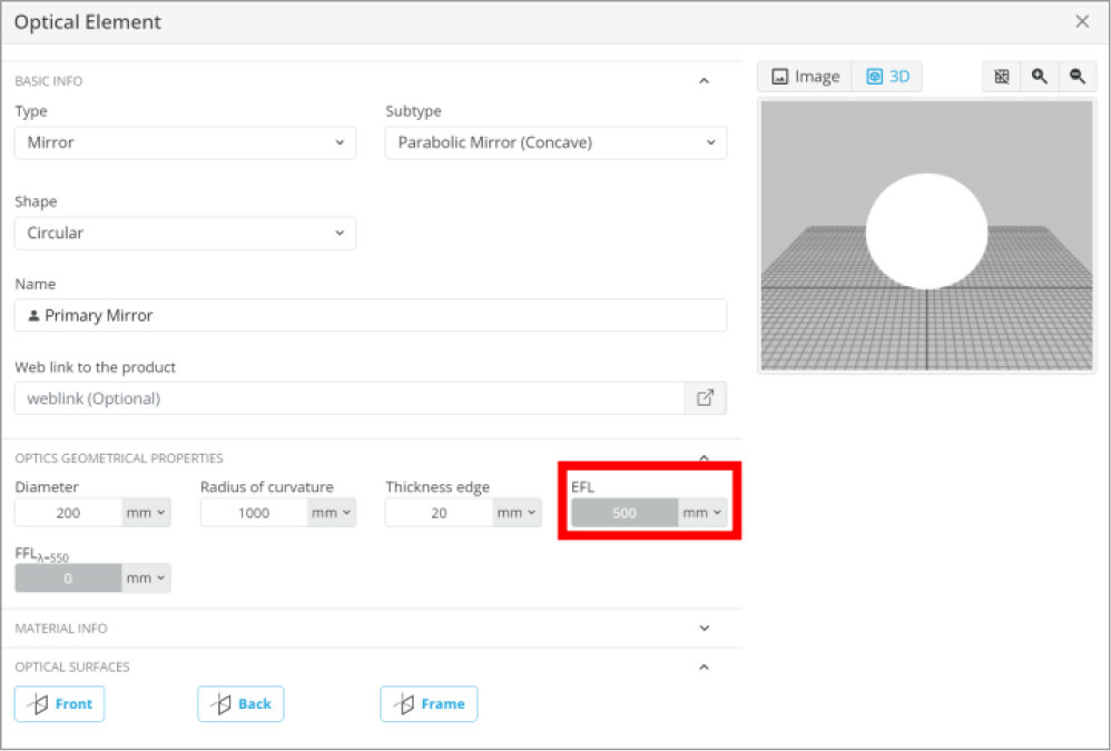
    • Focal Length: 500 mm
    • Ideal Reflective Coating
  3. Flat Mirror
    • Circular, 50 mm diameter
    • Ideal Reflective Coating
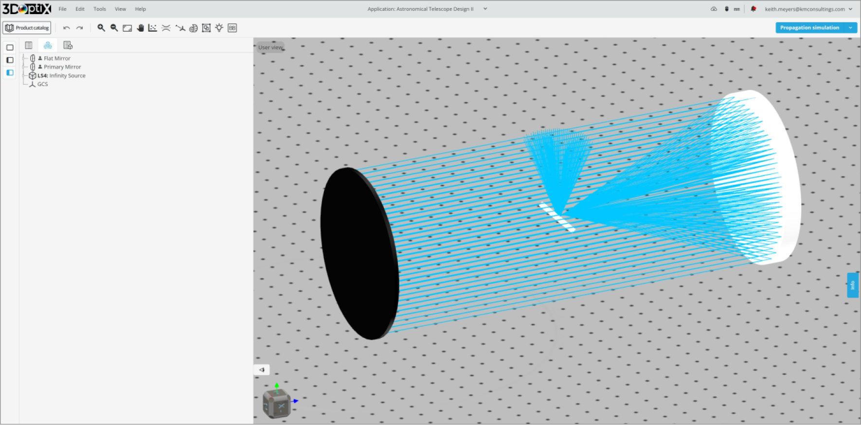
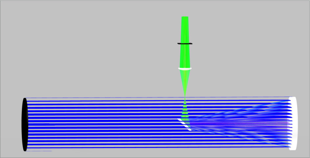
You can see the image of our optical system below. The 3DOptix simulation file can be downloaded to see additional information about the optical system such as component spacing and analysis detectors.
Some characteristics of the Newtonian Reflector telescope:
  • Wide field of view for observing larger astronomical objects
  • Inverted image
  • Good light-gathering characteristics
The Newton Reflector telescope uses a large parabolic mirror as the primary mirror to eliminate spherical aberration and a flat secondary mirror to redirect the light. As can be seen, the focal length of the system is longer than the actual telescope due to the path folding back on itself towards the flat mirror and then up towards the eyepiece (not yet shown).
The focal length of the primary mirror will be kept constant, and we will need to move the flat mirror into place to redirect the light output. This is a simple process as the flat mirror has no optical power. The only parameter we need to change is the diameter of the flat mirror, and this will depend on the placement of the mirror.
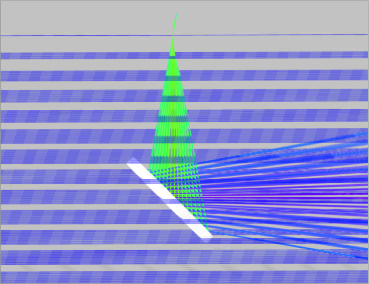
As the secondary mirror is moved towards the primary mirror the converging light overfills and misses the mirror. We need to increase the diameter to capture all the light from the primary mirror. We will increase the secondary mirror from 50 to 70 mm in diameter.
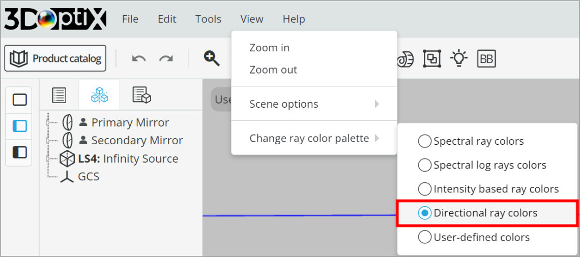
Additionally, we will change the ray colors to directional rays so we can easily see the converging rays incident on the secondary mirror.
Now we can observe if all the light from the primary mirror is hitting the secondary. It does appear that the secondary mirror is now large enough to capture all the light. One item to note is that the larger we make the secondary mirror, the less light overall will propagate through the system as it will block more input light.
With a nominal solution found, we can next add the eyepiece lens to collimate the light for viewing with a camera for this application. The lens we add must be at a distance that is greater than the radius of the primary mirror as it cannot exist in the light path. This means we also have to choose a lens focal length and diameter that will capture and collimate the light from the secondary mirror.
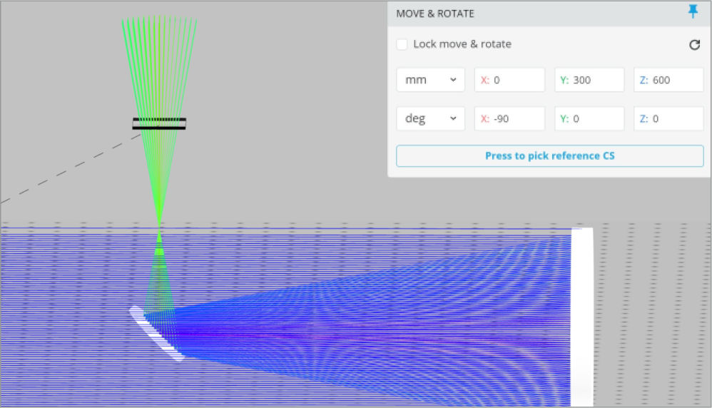
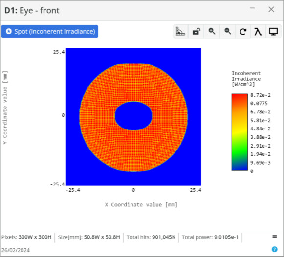
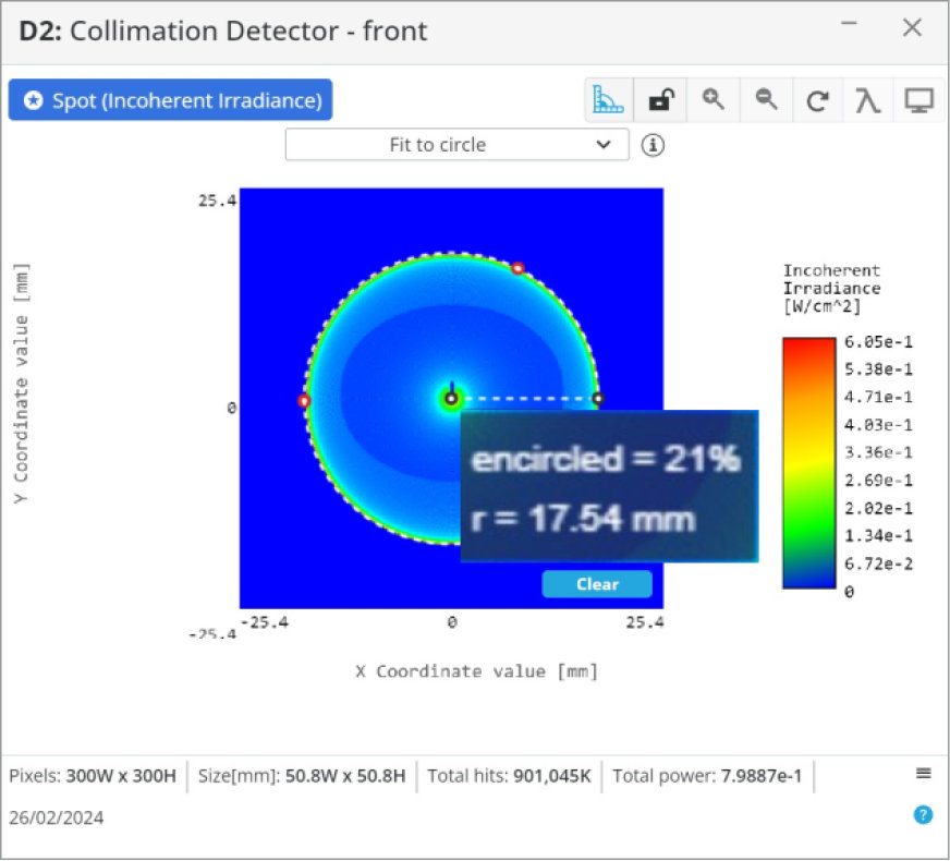
To make an initial guess on what lens we need, let’s add a detector and measure the spatial extent of the light 300 mm above the secondary mirror. This will generate a minimum eyepiece lens diameter as it must be at least this size to capture all the light incident from the optical system.
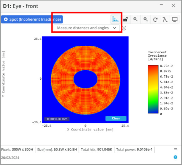
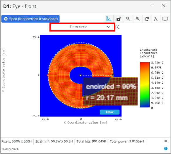
After the analysis is run we can see the spatial profile of the light from the secondary mirror at the detector location. We can use the measuring tool to measure the radius of the spot size, and more specifically fit to the circle. The radius is about 20 mm, so we will use a 50 mm diameter lens.

Now that the eyepiece lens diameter is determined, the focal length is the final parameter needed. We can place another detector approximately near the focus in the 3D layout to measure this, but it is easier to just use the focal length of the primary mirror and do a quick calculation.

The primary mirror focal length is 500 mm, and the primary to secondary mirror separation is 400 mm. The distance from the secondary mirror to the detector we placed is 200 mm. Using these numbers, we know a lens with a focal length of 100 mm needs to be placed where the detector is currently positioned
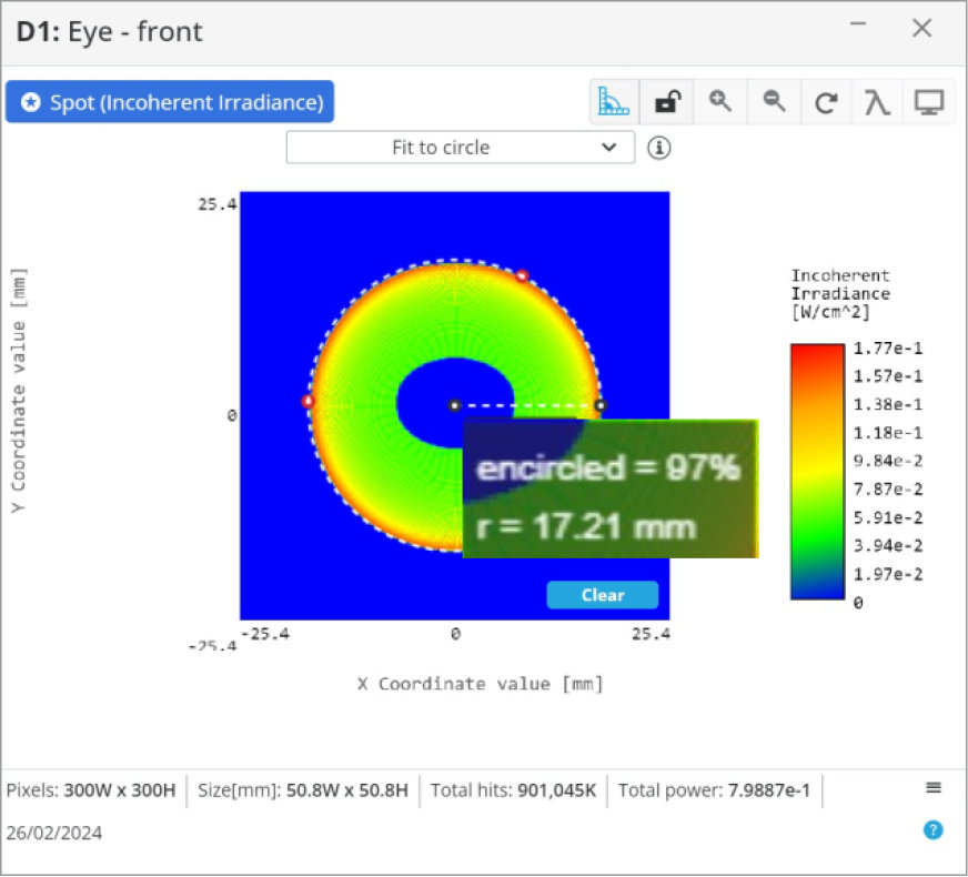
Placing the eyepiece lens at the nominal position we generate a good output from the system, but the light is slightly converging as can be seen in the image on the right.  We will want to move the lens towards the secondary mirror to better collimate the light.
To ensure we have good collimation a second detector will be placed 1000 mm from the first detector.  In this manner, we can test collimation by measuring the spatial extent at two locations that are very far apart.  If the measured diameter is the same at both positions, then we know the light is collimated.  This will change the spot size diameter slightly.
With the lens repositioned to 289 mm above the secondary mirror, the collimation becomes very good and the spot size is ~35 mm in diameter.

The last item we want to introduce is a 25 mm paraxial lens that simulates a camera lens and places the detector at the paraxial lens focus to simulate the focal plane array.

One note, if we wanted to create the telescope for viewing with an eye, we would want to use a smaller diameter and short focal length lens to create a smaller spot size. Otherwise, with the 40 mm spot size we currently have, the iris of the eye would block most of the light as it is only ~10 mm in diameter.
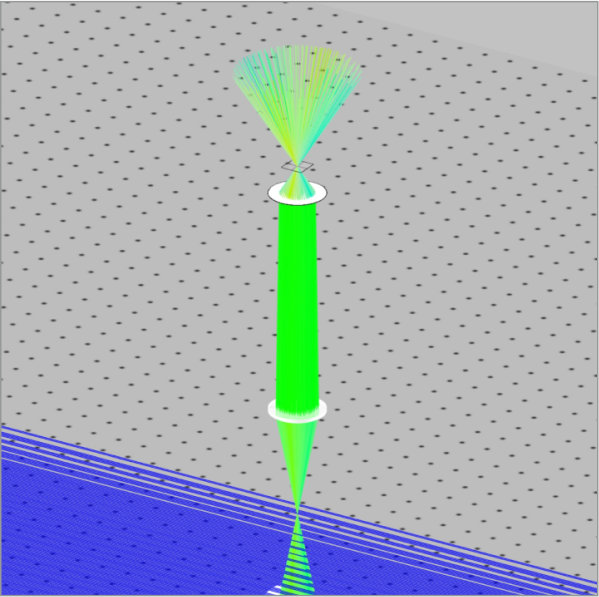
With all optical components in place, we can now estimate the magnification of the telescope design using the equation below:
  • System Magnification: M = \frac{f_{System}}{f_{eyepiece}} = \frac{500}{100} = 5x
If we desire a higher magnification, we can increase the focal length of the primary mirror or decrease the focal length of the eyepiece.
Now that we have a baseline design of a Newtonian reflector telescope, we can further change and test the optical configuration. Using known equations that are used for designing these types of astronomical telescopes we can further optimize and analyze the system. The analysis features we have access to will be very helpful in further efforts.
mascot-1-1

3DOptix works
only on desktop!

Please go to 3doptix.com on a
desktop device, using the
Chrome or Edge browser

Available on January 30th, 2023